0

Using answer about microphone I have built a simple amplifier.
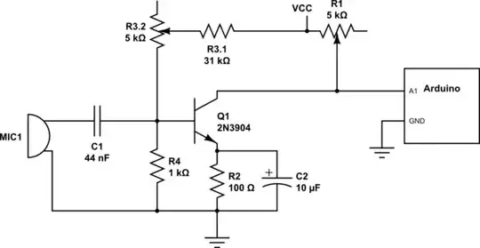
schematic

simulate this circuit – Schematic created using CircuitLab

I changed some of the parts due to my needs and resources.

  • R1: is now potentiometer and allows me to set the "0" of the sound to 2.5V
  • R3: should control amplification (but it doesn't seem to), so again a potentiometer
  • C1: unless the original answer meant electrolytic capacitor, there's no way to get 22uF capacitor. So I used just two 22nF caps.
  • C2: I have 10uF capacitor (salvaged from old sound card ironically), so I used that

So I have set up R1 to get 2.5 volts on silence. The image displays 80Hz sine wave rather than silence, I generated it here (works on Android).
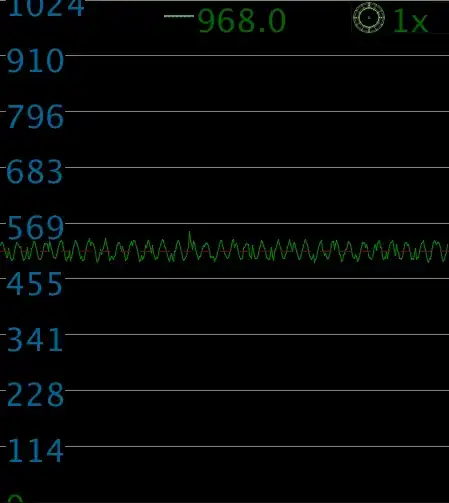
image description

Now if I move the R3.2, instead of change to gain, I just get voltage offset, and an insignificant one. Picture describes full range (min - max - min) of that particular potentiometer:
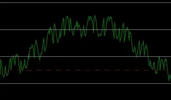
image description

Note also that increasing resistance increases voltage on output.

I could use my 50k potentiometer instead but that would give me no precision.

So what is wrong with my circuit? How to control the amplification?

Note: I displayed the analog input using this processing script and this arduino program, both mine but I thought I might share.

Tomáš Zato
  • 1,044
  • 4
  • 21
  • 40
  • AFAIK this circuit has a fixed gain. No gain control is available. It wholly depends on the voltage/current produced by the mic. Also, try moving your question to the start, as it got buried at the end. – Passerby Mar 16 '16 at 21:08
  • Also your values seem odd. The R3 is 36k, to R4 1k? That would be 0.14V center, not 2.5V. – Passerby Mar 16 '16 at 21:10
  • And Oli recommended C1 to be 1µF or greater. A 1uf ceramic would be fine. – Passerby Mar 16 '16 at 21:12
  • Oh, essentially to change the gain without the offset change, R3 and R4 need to be changed, proportionally, lower. – Passerby Mar 16 '16 at 21:23

2 Answers2

1

Try this...

  • Remove R1 the way it is currently wired and all wires leading to it.
  • Connect a ~1k resistor from Vcc to the transistor collector.
  • Connect R1's end leads from the transistor collector to ground, respectively. A larger value for R1 might be a good idea, such as 10k, but it isn't critical.
  • Connect a 1µF ceramic cap from R1's wiper to the arduino.

Edit:

  • Also connect a 10k from Vcc to the arduino pin, and a 10k from that to ground. This will cause the output to center around 2.5v, which seems to be what you are after.

This way, the position of R1 forms a "tap" between full signal, and no signal. Then adjust R3's value to give the cleanest output with the loudest microphone signal expected. There is a technical term for adjusting these resistor values - biasing. Also this. Have you calculated what the values should be?

rdtsc
  • 15,913
  • 4
  • 30
  • 67
1

Your gain will be approximately $$a=-\dfrac{R1}{R2}$$ As you modulate the base voltage, the emitter voltage will increase by a roughly equal amount. This increases the current through R1. Almost all the current through R1 also flows through R2, causing a voltage drop.

After choosing the gain you want for your circuit, you'll need to adjust the bias using R3 to maintain your 2.5V zero point.

$$V_e = \dfrac{2.5V\cdot R2}{R1}$$ $$V_b = V_e + 0.7V$$ $$V_b = \dfrac{V_{cc}\cdot R4}{R3 + R4}$$

One more thing to keep in mind is the size of your 44nF capacitor. It will create a highpass filter with cutoff frequency $$f_c = \dfrac{1}{2\pi\cdot (R4||R3)\cdot c_1}$$ With the current values you have in there this comes out to be over 3kHz. You can hear much lower than that so I recommend choosing a larger capacitor.

rdtsc
  • 15,913
  • 4
  • 30
  • 67
user103923
  • 41
  • 1