4

I am trying to build a Wien bridge oscillator that oscillates at 2.1kHz and that can be switched on by a transistor. The reason for me placing a transistor switch in the circuit is so that I can turn the oscillator on and off from a PIC MCU. However, when I build the simulation in multisim, I get an DC output voltage of 3.0mV and an. I want an output voltage of 5.0V p-p, so can anybody explain to me what the problem with this circuit is? Any help would be much appreciated.

enter image description here

PeterJ
  • 17,131
  • 37
  • 56
  • 91
D Brown
  • 781
  • 2
  • 16
  • 23
  • @D Brown: Disconnecting one of the supply rails will stop oscillations - and produce an undefined dc output at the opamp. Can you live with this? Why not stopping the oscillation by disconnecting the frequency-dependent positive feedback path from the opamp`s output - and leaving the resistive feedback untouched? – LvW Sep 25 '14 at 12:18

2 Answers2

4

Your opamp only has a gain of 1.
A wien bridge oscillator needs a gain of 3 to compensate for the attenuation of the RC network at the freqeuncy of oscillation.
Try adding the neccessary feedback resistors for G = 3. You would typically need some AGC (automatic gain control) in a real circuit, possibly here too.

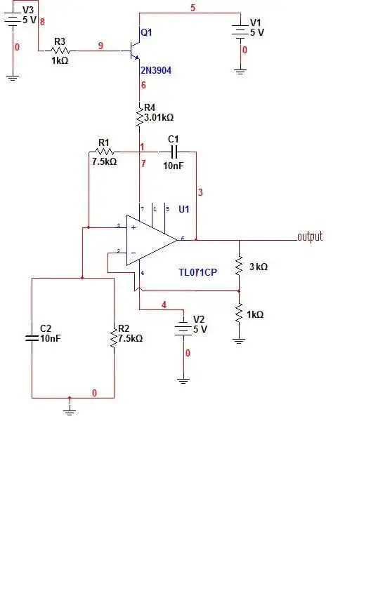
EDIT - I just noticed the 3.01k resistor (R4) on the V+ pin of the opamp. What is this for?
It will certianly cause strange behaviour as the opamps supply voltage will vary according to how much current it draws.
To simplify things I would get rid of R3,R4,Q1 and V3. Just use V1 to supply 5V directly to the V+ pin (pin 7)
If you could update your diagram with the new version (with gain setting resistors, etc) it would help to be sure you have it right.

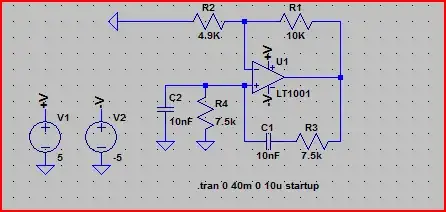
EDIT 2 - I just tried this in LTSpice:

Schematic:

Wien Bridge

Simulation:

Wien Bridge Sim

There are two things to note here. One is the use of a gain slightly higher than 3 (R2 + R1)/R1 = 14.9k / 4.9k = ~3.04.
The other is the inclusion of "startup" in the .tran command. This tells it to start the supply voltages at 0, giving the oscillations a chance to start before the circuit has reached a steady state. Otherwise you would have to inject some noise into the circuit to simulate real world conditions. You should have a similar setting in MultiSim (e.g. "start supply voltages from 0" box to tick or something like that)

To include an AGC, you would use something like a thermistor in the feedback path (e.g. between R2 and ground) When the gain rises above 3, the thermistor passes more current and raises it's resistance, thus dropping the gain. You can also use a JFET, diodes, bulbs, etc. I wouldn't worry about this now though as you can get the circuit to work without this. The main purpose is to stop clipping/distortion of the sine wave which would be bad for e.g. a signal generator.

EDIT 3 - Limiting current with a resistor is not necessary, the TL071 will only draw as much current as it needs so you can connect it directly to the voltage source. The amount of current the supply could provide is irrelevant, the TL071 will draw max 2.5mA whether connected to a 5V 3mA supply or a 5V 300A supply.
To switch the power on and off, a P-channel MOSFET would work okay. You would tie it's source to +5V, drain to opamp V+ and gate to microcontroller pin. Set pin to 0 to turn on, 1 to turn off. If microcontroller supply is lower than 5V, then you would need a pullup resistor from gate to +5V (say 10k). Set pin to Hi-Z (e.g. input) to turn off, set to output and 0 to turn on.

EDIT 4 - An N-Ch MOSFET wouldn't work very well, as when you turn it on (e.g. gate to 5V), the source voltage rises and narrows the difference between the gate and source again. It will ultimately settle at around Vgate - Vt. So if the Vt (voltage required to turn on = threshold voltage) is say, +1.5V, and the gate is set to +5V then the source would only reach 5 - 1.5 = 3.5V. Since the source is connected to V+, then the opamp will only see 3.5V for it's positive supply.

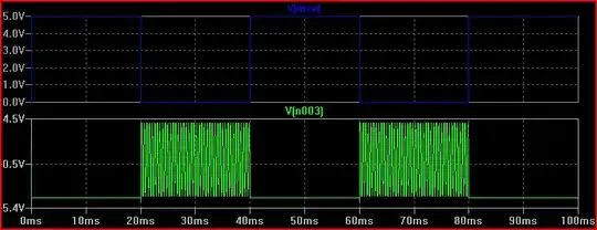
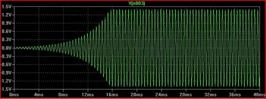
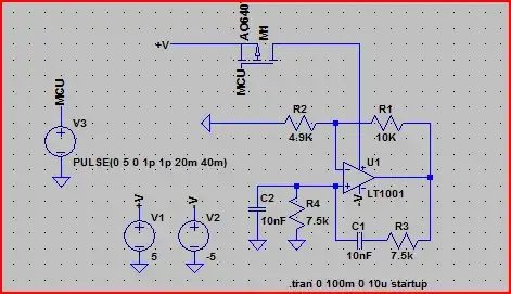
Here is an example of the switching. Note how when the mcu pin (represented by V3) is set to 0 the oscillations start and vice versa:

Schematic:

Wien Bridge Switch

Simulation:

Wien Bridge Switch Sim

Oli Glaser
  • 54,990
  • 3
  • 76
  • 147
  • Thanks but how could I place AGC in the circuit? – D Brown Nov 13 '11 at 19:58
  • So I've tried your suggestion and added a G=4 to the crcuit but now the simulation crashes...any suggestions on how to correct this? – D Brown Nov 13 '11 at 20:17
  • Contact Multisim? It shouldn't crash. – Leon Heller Nov 13 '11 at 20:25
  • @LeonHeller- So the circuit design itself is ok then? – D Brown Nov 13 '11 at 20:40
  • It doesn't look right to me, FWIW. – Leon Heller Nov 13 '11 at 20:49
  • @LeonHeller - I'm sorry, but what does FWIW mean? – D Brown Nov 13 '11 at 20:52
  • @DBrown - see edits. No idea why it crashed, though oscillator circuits can be quite difficult to simulate in SPICE. Try the suggestions and let us know how it goes. – Oli Glaser Nov 13 '11 at 20:57
  • @OliGlaser- The purpose of R4 is limit the current flowing through transistor Q1 as the TL071 op-amp has a max supply current of 2.5mA, and the purpose of R3 and V3 is mimic the MCU sending a logic HIGH volage to Q1. I need to able to turn on the oscillator on and off using a MCU. Could you suggest an alternative solution then, seeing as this design has some flaws? – D Brown Nov 13 '11 at 21:20
  • FWIW - For what it's worth! – Leon Heller Nov 13 '11 at 21:39
  • @OliGlaser - Thanks for the idea of the P channel MOSFET. – D Brown Nov 13 '11 at 21:44
  • @OliGlaser- If I use a N channel MOSFET, I would have to set the MCU pin to 1 to turn it on and 0 to turn it off then. – D Brown Nov 13 '11 at 21:54
  • @Dbrown - See edit 4, an N-ch MOSFET won't work as well. – Oli Glaser Nov 13 '11 at 22:09
  • @Oli Glaser - I only have access to P-channel JFETs in my school lab, can I use one of those? If I can, how would I use it? – D Brown Nov 13 '11 at 22:56
  • @DBrown - No, a JFET won't work. If you have no P-ch MOSFETs then you could use a PNP transistor. Emitter to +5V, collector to opamp V+, base to MCU pin via a 10k resistor should work okay. – Oli Glaser Nov 14 '11 at 00:09
  • @OliGlaser, I've not had must experience with using JFETs. Why would one not work in this application? – sherrellbc Jul 29 '14 at 13:17
  • "how could I place AGC in the circuit? " There are several ways to softly limit the amplitude: NTC, PTC (lamp), diodes (antiparallel), FET control loop,...It really depends on your needs/requirements (THD). – LvW Sep 25 '14 at 10:27
0

I think that if you make a slight modification to your circuit to operate as a wien bridge oscillator, the gain should be equal to 3, I added to your circuit 3k and 1k 3/1=3 you may need to reduce the value of the resistor R4 to 10 ohm or short it (make it equal to zero)

and replace q1 with a power transistor like BD135. enter image description here

m salim
  • 402
  • 2
  • 15
  • The (non-inverting) gain of the circuit above is 1+3=4. This excess gain drives the output too much into saturation (heavy signal clipping). – LvW Sep 25 '14 at 10:24