8

enter image description here

I know that the there is two lines to connect it to the integrator like the below picture , so what the 3rd line do? how to use it? is it necessary?

enter image description here

Davide Andrea
  • 16,164
  • 4
  • 33
  • 62
xsari3x
  • 1,608
  • 5
  • 27
  • 42
  • 1
    I can't find a datasheet for it ... It doesn't have any part number or anything .... just a plain metal ... – xsari3x Nov 12 '11 at 13:36
  • From what I can see (though the data sheets I have found are very very lacking in any detail whatsoever) the blue and yellow are connected to one end of the resistance, and the green to the other end. Use either the blue or the yellow, it doesn't matter which. I guess there may be situations where you want to connect two things to one side of the shunt maybe? – Majenko Nov 12 '11 at 13:48
  • @Majenko Great , but I'm sure there's a reason or situation as you said – xsari3x Nov 12 '11 at 13:53
  • 1
    I'm puzzled by three wires. 2 or 4 would make sense. 4 leads from a high current shunt are not unusual. That allows you to measure the voltage drop accross the resistance only without the drop accross any connections getting in the way. Maybe this is a special part and the third wire is a tap part way to provide alternal resistance? What do you get when you measure with a low value Ohm meter? – Olin Lathrop Nov 12 '11 at 13:55
  • I'm making a current metering circuit (AC) ,I will use it in a high side shunt measuring , what do you mean by 4 wires ?? is there any more info you need me to provide ? @OlinLathrop – xsari3x Nov 12 '11 at 14:01
  • The left hand unit has a code shown on it. What does it say? – Russell McMahon Nov 12 '11 at 14:50
  • @olin I have been looking through suppliers lists. 3 wires isn't that unusual, but (mostly Vishay) the data sheets don't actually tell you what the wires do. – Majenko Nov 12 '11 at 15:03
  • RX300 , this what's written , but the one I have doesn't have this – xsari3x Nov 12 '11 at 15:11
  • 1
    High sensitivity and low sensitivity measurements? You might find the resistance between (blue/yellow) and (blue/green) is different by a factor of 10. – Optimal Cynic Nov 12 '11 at 21:04
  • The picture suggest that the blue wire is thinner than the other two. Is this the case? (But if so it would make even less sense to me...) – Wouter van Ooijen Nov 12 '11 at 22:13
  • @OptimalCynic are you sure or is it a guess ? – xsari3x Nov 12 '11 at 23:47
  • @WoutervanOoijen mine are the same size ... no sense at all , I checked alibaba & globalsources lot of suppliers sell it with 3 wires ? but no datasheet ! – xsari3x Nov 12 '11 at 23:48
  • any update /new data ? – xsari3x Nov 14 '11 at 03:09
  • 1
    The 3-wire configuration most certainly is a variant of a normal 4-terminal-sensing circuit, like here: http://en.wikipedia.org/wiki/Four-terminal_sensing (scroll down). – 0x6d64 Nov 14 '11 at 08:11
  • @0x6d64 I guess this is what is it about. – xsari3x Nov 14 '11 at 14:14
  • @0x6d64 mmm After searching shunt resistance is used to measure the current(I) value , but what you provided is used to measure the resistance value ! – xsari3x Nov 14 '11 at 15:22
  • @xsari3x: There are some circuits which will take three inputs voltages, and report an output which, if connected to the three colored wires shown, would be proportional to V(GY)-2V(BY), on the assumption that the voltage drop of the yellow wire will be roughly equal to that of the blue wire. Such a thing could offer better accuracy than a two-wire shunt, but I'd worry about things like variations in soldering. A four-wire shunt would seem the most natural way to measure current. – supercat Nov 14 '11 at 16:30
  • @xsari3x: You are right. After thinking a little about your original picture, I ask myself if the two metal strips are screw terminals (which would make sense for a shunt, as you would expect a big current). Then the device would have 5 terminals, but I can't make any sense of that additional terminal. However, vishay sells shunts with 5 terminals: www.vishay.com/docs/30160/wsms2908.pdf – 0x6d64 Nov 14 '11 at 16:45
  • 2
    @0x6d64, write that. It has two terminals that are higher power for your connection(the screw terminals you noted), then three terminals on the device for measurement. That is 5 terminals. – Kortuk Nov 14 '11 at 18:00
  • When I will be able to put a bounty ? – xsari3x Nov 14 '11 at 18:50
  • @xsari3x, should be able to now, minus any rep requirement, which you can look up by looking at your privileges. – Kortuk Nov 15 '11 at 07:27

1 Answers1

6

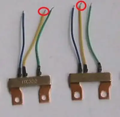
These are current shunt device sold for use with KWh meters. As Kortuk notes, these are 5 wire devices - not 3 as may appear.

2 of the 5 "wires" are hard bolted connections to the "copper" frame.

Current flows between studs or bolts which are inserted through the two holes so the main current flow is via the copper strip.

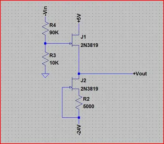
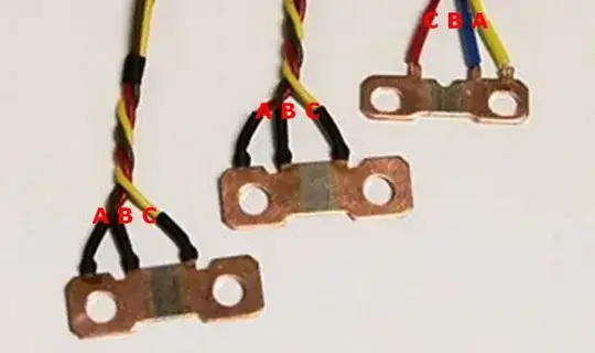
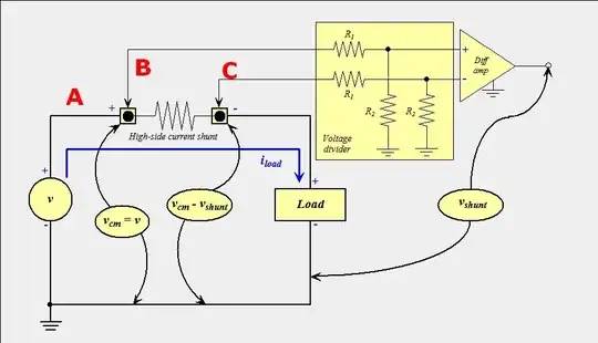
If you take the diagram you provided at face value (see anotated version below) it shows exactly what is being done.

  • The two stud holes make contact with the power circuit.
    B is the power input side. C is the load side
    Th sense element is usually constantan.

  • So BC measure a voltage proportional to load current.

  • A is used to measure the input voltage = the common mode voltage in the diagram. The diagram does not show A being used BUT in a "real" system the 2 x R2 resistor could be returned to A if desired instead of ground.

  • Va and Bc are very similar - the voltage drop across half the terminal is the only difference, This could be used but may not be.


Note that A & C leads have the same colour code in all 3 devices while B varies.

B & C leads connect hard up against the sense element. The voltage drop that they see is caused essentially solely by the sense element. If you want to sense current based solely on this devices sense element these are the leads to use.

However, the A lead connects to the side of the bolted portion at one end. There will be minimal current flow in this area so it will assume the potential of the input "stud" less any contact voltage drop. There will be SOME voltage drop across the "copper" frame but this would usually be liable to be small. However, what voltage drop there is will appear across leads A-B and be able to be measured by the test system.

As per diagram, A is used for voltage sensing while B-C is for current sensing.

enter image description here

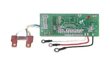
kWh meter PCB & resistor

enter image description here

enter image description here

What it does seems clear enough.
The question is, still, why?

Possible only:

  • If there is temperature rise in the copper then the ratio Vcopper / Velement will vary.
  • The voltage Va-b will be small in all cases. This could allow monitoring in a different way to the higher voltage Vb-c.

The above sold here

Similar sold here

kWh meter PCB for use wih these devices

Davide Andrea
  • 16,164
  • 4
  • 33
  • 62
Russell McMahon
  • 147,325
  • 18
  • 210
  • 386