3

I'm relatively new to EE, sorry if this is newbie territory.

With an Arduino, I am trying to emulate a device that outputs NEGATIVE 3.3v PWM (0V or -3.3V, square wave) at around 500 hz.

Obviously, the PWM out of an arduino is 0V or +5V (or +3.3v depending on the arduino) but there is no way to output negative voltage.

I've researched feeding the signal through a ICL7660 but it's unclear if the 7660 will produce a clean-enough negative square wave.

I also researched the MAX749, which will produce a negative voltage from a PWM, but it's unclear to me if the MAX749 will actually output a negative PWM square wave, or if it will instead output smooth negative (but variable) voltage output based on the duty cycle of the input PWM'd positive voltage source.

I've also heard that maybe I could accomplish this with a MAX232 since the RS232 standard has negative voltage signals as part of the communication standard but have no clue how to go about this.

Thoughts?
DrJustice
  • 31
  • 1
  • 4
  • Optocoupler should do. – Tom Carpenter Mar 08 '16 at 04:09
  • 1
    A 5 V zener in series with a pull down (to -3.3 V) resistor. When the arduino outputs 5 V the zener drops about 5 V leaving the output at 0 V. When the arduino outputs 0 V the zener doesn't conduct and the resistor pulls the output to -3.3 V. You of course need a regulated -3.3 V supply. – jms Mar 08 '16 at 04:25
  • I'm too much of a newbie to wrap my head around both responses -- I'd need a drawing or a better explanation for how to wire stuff... – DrJustice Mar 08 '16 at 04:46
  • 1
    Why (specifically) do you need a -3.3V PWM output? Is there any way you could simply attach GND of the receiving device to the arduino's +3.3V rail, and use the regular +3.3V ;WM output with an inverted duty-cycle? – Robherc KV5ROB Mar 08 '16 at 05:11
  • @Robgerc: I'm trying to build a home-made controller aimed to replace this: https://www.youtube.com/watch?v=oV96XcGfjpk The connector has 4 pins. +24V, 0V, PWM1 (white LEDs/daytime), PWM2 (blue LEDs/night time). The Wifi gizmo's PWM goes to a microcontroller hosted inside the LED fixture, which in turn modulates the brightness of the light. With an oscilloscope, I've measured the PWM to be from 0 to -3.3v, so I am trying to replicate the behaviour of the Wifi light controller. – DrJustice Mar 08 '16 at 05:30
  • BTW, I understand I can probably generate a PWM if I had a -3.3v source to begin with (as it was suggested above) but then I'm back into icl7660 or max749 to generate the -3.3v from a positive source. – DrJustice Mar 08 '16 at 05:36
  • I wonder if you got the measurement backwards? Could it be that the signal is actually 0 to 3.3V – Tom Carpenter Mar 08 '16 at 06:35
  • I wondered the same thing and colleagues asked the same thing so we double-checked. But no, there's clearly only one 0V wire, and when I measure it against the 24V wire with a scope, I read a positive 24V, but when I test against both PWM pins, I read -3.3v. – DrJustice Mar 08 '16 at 06:50
  • Oh, also, when I put the oscilloscope's probe on 0V and the reference on the PWM, the scope goes all crazy-nuts. – DrJustice Mar 08 '16 at 06:54

1 Answers1

3

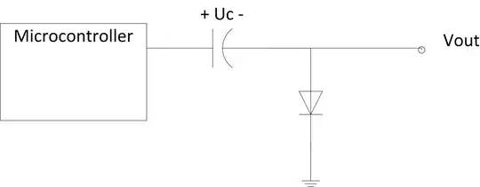
You can use the following circuit:

enter image description here

If the microcontroller generates a positive PWM signal, the diode will charge Uc to its maximum value (i.e. a constant value of 3.3 V or 5 V depending on your microcontroller).

Then $$Vout=-Uc + Vin$$ and therefore Vout will swing between 0 and -3.3 (or -5 V) as you want. This assumes a perfect diode with a 0 V drop, I guess that a Schottky diode should be fine for your application.

Roger C.
  • 2,205
  • 1
  • 9
  • 12