0

you see, i have this circuit

schematic

simulate this circuit – Schematic created using CircuitLab

however when i add another more 74161

schematic

simulate this circuit

the first one stops working and it just alternates between Qa and Qb LEDS i think it's because of the current needed, however im using a pc 600 watts power supply, any idea of what's going wrong?

  • Do you have power supply bypass capacitors (0.1 uF ceramic) between the power and ground pins of both 74LS161s (as close as practical to the chips)? – Peter Bennett Mar 06 '16 at 07:46
  • What you see is what's plugged in, where should the capacitor go? i really got no idea i had to make that ^^" – user145708 Mar 06 '16 at 07:50
  • 1
    As I said, you need 0.1 uF (or so) ceramic capacitors connected between the Vcc and Gnd terminals of each 74LS161, with as short leads as practical. These bypass capacitors are good practice in all digital circuits. – Peter Bennett Mar 06 '16 at 07:53
  • i dont have one at hand, will buy it tomorrow i guess, also do you think this will fix the issue? or is this for making my circuit safer? – user145708 Mar 06 '16 at 07:54
  • Suggested reading: http://electronics.stackexchange.com/questions/15135/decoupling-caps-pcb-layout and http://electronics.stackexchange.com/questions/59325/whats-the-use-of-a-decoupling-capacitor-near-a-reservoir-capacitor – MarkU Mar 06 '16 at 09:11
  • What's most likely happening is that the supply voltage *at the IC pins* is briefly dropping too low, due to switching current transients. Even if the supply can provide 600 watts, it's effectively "too far away" to be effective against those fast transient current events. The inductance of the long wires prevents the supply's regulator from responding quickly enough to meet the demand. Adding a small ceramic 0.1uF capacitor, with very short leads, very close to each IC, stores enough charge locally to supply the immediate demand and keep the supply from sagging. – MarkU Mar 06 '16 at 09:18

1 Answers1

1

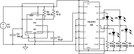
OK, first things first. Multiply R1 and R2 by a factor of 100, and reduce C2 by a factor of 10. Frankly, I'm surprised that your 555 will work reliably with such small resistors.

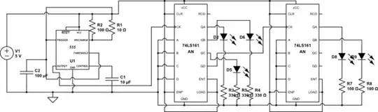
With the 555 done right, look at the counters. As has been suggested, you need a decoupling capacitor for each counter. You also should add a larger capacitor, like 10 to 100 uF between +5 and ground near the counters. Depending on how you have your circuit wired up (long, small-diameter wires from the power supply?) this may or may not be important, but it won't hurt - as long as you don't connect the caps backwards, of course.

You are driving your LEDs wrong. TTL and LSTTL do not do well sourcing current. That is, they don't provide much current for loads to ground. What they do much better is sinking current, so your LEDs should be connected like

schematic

simulate this circuit – Schematic created using CircuitLab

Here I've shown the first LED as being On when the logic from the chip is 0, which you may find confusing. So the obvious solution is to add an inverter and drive the LED that way. If you do add an inverter, you don't need the first LED.

Another thing to be careful about is your ground connections. I'm not sure what you're using for construction. If you're using a solderless breadboard, make sure your connections from pin 8 to the ground strip is as short as possible. Also, make sure your 0.1 uF caps (ceramic, please) are connected directly to the sockets immediately adjacent to the IC pins. Do not put the capacitor somewhere else on the board and then run jumpers to the ICs.

WhatRoughBeast
  • 59,978
  • 2
  • 37
  • 97
  • Thanks!!! The problem was that thing of the bypass capacitors! And thanks I will change the 555 properties! Damn 3 days thinking about what was happening really, you are great guys – user145708 Mar 06 '16 at 16:09