3

For my project I'm using a nRF51822 SoC with a CR2032 powering it. I'm using an LED with 1.5mA consumption to signal a rare event. The LED has to have 2 V to work.

As the battery discharges, the voltage drops from 3.3V down to 2V when its empty. For the majority of time its voltage is around 3V.

When the Battery is close to empty, the microcontroller still works, but the LED doesn't.

What would be the best way (the simplest) to power that LED, even when the battery voltage falls?

Currently its just connected to a microcontroller with a 510 ohm resistor in series, since it's ok for the led to get 2V to 2.4V.

Passerby
  • 72,580
  • 7
  • 90
  • 202
Lazyboy
  • 525
  • 1
  • 5
  • 19
  • What's the minimal voltage (requirement) that your system should be up and running? – PDuarte Mar 02 '16 at 11:02
  • Simplest would be using an led with a lower Vf at a usable If. And your powering a SOC on a cr2032? Have you taken the cells ESR into account? – Passerby Mar 02 '16 at 11:30
  • I don't understand your parameters. Are you talking about adding a second power source, and gating the LED when it uses that power source, or creating a higher voltage supply from the existing supply? – Scott Seidman Mar 02 '16 at 13:39
  • 1
    a CR2032 should be considered dead at 2V, what is the Vin min for your system. Also the only good easy answer is find a LED with a lower Vf. – MadHatter Mar 02 '16 at 14:17

3 Answers3

3

If you don't mind a few more parts you could connect the LED to a voltage doubler, but you'd only get ~half the LED current for the same input current.

schematic

simulate this circuit – Schematic created using CircuitLab

(not shown) use a large bypass cap across the battery- 100uF would be good.

Or just find the LED with the lowest Vf you can find (it will be a red color).

Spehro Pefhany
  • 376,485
  • 21
  • 320
  • 842
1

I think the simplest way is one of two options:

  1. Replace the LED with one with a smaller VF at the desired IF (and/or brightness).

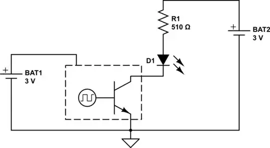
  2. Add a second battery to extend the whole battery life, or just for the led.

schematic

simulate this circuit – Schematic created using CircuitLab

In this case, you will need to reverse the led logic. Only 1 extra part, and could be a smaller button cell instead of a cr2032.

Passerby
  • 72,580
  • 7
  • 90
  • 202
0

The lowest component count for your particular problem, I think, is a MOSFET current mirror, as such:
schematic

simulate this circuit – Schematic created using CircuitLab

M2 will start conducting when its gate is at a voltage that allows the required current to flow through R2, so that its drain and gate together create a nice little set-point, which applies to the gate of M1. M1 will then start conducting.

In theory, if both MOSFETs have the same voltage dropped across them it will be the exact same current, since their gate voltages are exactly the same, but of course in reality there will be discrepancies, since your LED takes up more voltage than R2 likely will. There are solutions for that as well, but they will take up more voltage headroom.

I did a quick Farnell search (because I'm limited in my time and a tiny bit lazy on Wednesdays) and found the Fairchild FDV301N, with a nice Datasheet with all kinds of cool graphs.

What's important here is that you find a MOSFET with an active region at gate voltages well below 2V. If you look at Figure 1 in the datasheet linked above, you will see that at Vg = 1.5V it still is able to conduct a few mA while having less than 0.1V required across its Drain-Source segment.

For M2 the drain-source voltage will be higher, because of the balancing act with Vg explained above, so there it doesn't matter much, but you want your M1 to conduct with as low a voltage drop as possible when your battery is close to 2V.

R3 is there to increase the balance between the MOSFETs. If one wants to conduct too much, R3 will push them both closed until it balances back out.

I expect (huge ball-park-top-of-head numbers:) at 2V battery about 1mA through the LED, while at 3V about 5mA through the LED. But these are just very rough estimations as are the two resistor values, you should experiment a little with different values if the current is wrong for you in the real world.

If it changes too much with battery voltage you want to tweak R3 until the ratio is good enough, then if the exact current is wrong you tweak R2 until that is right. Both resistors influence both parameters, but R3 has a stronger influence on balance and R2 has a stronger influence on current set point.

You should note though, that with this trick you'll be wasting a tiny amount of extra energy when the LED is on, because of the current going through M2, that isn't used to light up the LED. If this only 1 second every hour, you can imagine that the influence of the current through the LED is microscopic compared to the SoC's consumption throughout that hour.
Asmyldof
  • 18,299
  • 2
  • 33
  • 53
  • 1
    ALD1101 or ALD1116 wouldn't need R3 and are still good enough to deliver 1 mA at 0.1Vds. You also don't have to worry about threshold mismatching and its effects on the the current mirror (since those are *designed* to be current mirrors). – Dave Mar 02 '16 at 12:03
  • Current mirror will not be helpful if the forward voltage requirement of the LED is higher then the battery voltage... – MadHatter Mar 02 '16 at 14:56
  • @MadHatter generally if your LED Vf is higher than the battery voltage in a low-power device, my advice is, get a better LED or better battery. Lowest Vf for Red/Orange/Yellow LEDs at 1mA in my stock is 1.6~1.7V, so there's even colour choices. – Asmyldof Mar 02 '16 at 19:07