2

I have used the innards of a Korg Mini-KAOSS Pad to add some amusing effects to one of my electric guitars, but in order to do this I had to remove the original input connectors and wire my pickups directly to the input circuitry.

The input voltage is fine, however I do now have a problem with a high pitched digital sounding whine when using effects. My assumption is that the input connectors probably had some type of rolloff circuitry (almost certainly passive) and in removing these I am getting interference from the high frequency oscillators in the DSP circuitry.

As part of my remediation I am increasing shielding, but realise I probably need to add a filter to remove higher frequencies.

tl;dr - is there a simple circuit (ie probably just an R/C) that I can pop in to roll-off rapidly above the usual frequencies I would get from my guitar strings?

Oli Glaser
  • 54,990
  • 3
  • 76
  • 147
Rory Alsop
  • 604
  • 9
  • 25
  • 2
    Removing noise from a signal is almost always the wrong approach. You need to figure out how the noise is getting into the signal in the first place and prevent that from happening. – endolith Nov 09 '11 at 21:44
  • Did you previously connect the guitar *through* the connectors and not have this noise problem? – endolith Nov 09 '11 at 22:03
  • I previously connected it through the connectors and all was well. Since then the miniKP has been disassembled, which does include removing the metal box - hence the shielding - as well as removal of the input section. – Rory Alsop Nov 10 '11 at 08:58
  • The "input section" you removed is just the jack, though, right? And you connected the wires to the same pins that they were previously connected to through the jack? So it's probably the shield removal that's the problem. It might not be a shielding issue so much as a shared ground issue. Your guitar input isn't earth-grounded anywhere is it? – endolith Nov 10 '11 at 14:39
  • well - it was a small daughter board with the input sockets and a small amount of surface mount circuitry. Tricky to tell what the components are but I'm erring on the side of DC decoupling capacitors. – Rory Alsop Nov 10 '11 at 15:02
  • Ohhhhhhhhhhhh. Well. That's the reason. Post a picture of the important components that you removed from the circuit. – endolith Nov 10 '11 at 16:26

3 Answers3

4

Can you show us a picture of exactly what you removed? (and maybe the input circuitry) Any filtering will likely take place after the input amplifier, so it's possible something else is happening.

It certainly wouldn't hurt to add a simple RC filter just in case though, then if the problem persists you know it's something else.
If you do this I would go for something like Olin suggests but adjust the values for your guitar pickups (e.g something like 100k for R1) which will probably be higher than 600 \$\Omega\$.

For line level connections, old equipment was often matched 600 \$\Omega\$ in/out. Nowadays however it's usually Lo-Z out to Hi-Z in. The Hi-Z input is often 10 k\$\Omega\$, but can be higher. You could measure the resistance across your Mini KAOSS input (be sure to do it after any DC blocking cap if present) to find out exactly what you are working with. YOu could also measure your pickups DC resistance to get a rough idea there too.

I can only see a line in connection, which will probably be expecting a lower impedance signal than your guitar can provide. Have you tried putting your guitar through a preamplifier/DI box?

There may possibly be a DC blocking input cap you may have removed, which might cause strange things to happen.

Here is a clip of a typical guitar amp input to give you an idea of what it expects to see. Note the 1 M\$\Omega\$ input resistor.
I'm no expert on guitar (passive coil) pickups but I think they are commonly around 5-20k (varies with frequency)
A piezo pickup will be much much higher.

Guitar amp input

Oli Glaser
  • 54,990
  • 3
  • 76
  • 147
  • I was toying with building in a pre-amp, but I'm running out of room inside my guitar. Think I will test with an external preamp and come back to this one. Hadn't thought of DC blocking - good call. – Rory Alsop Nov 09 '11 at 14:55
  • You can make them very small and simple - I made a little 2 transistor one for an old Strat I had. You could even get away with just using one. – Oli Glaser Nov 09 '11 at 15:11
  • Definitely try with a DI box in between the guitar output and line input. With the guitar's 250 kΩ volume pot at half, you're already greater than 125 kΩ output impedance, ignoring the impedance of the pickup itself. Piezos are in the MΩ output impedance and should never be run directly into a cable anyway. – endolith Nov 09 '11 at 22:00
  • 1
    @endolith - not that it affects your point, but if the pot is connected in the standard way (signal top/bottom, out from wiper) then the halfway impedance is 62.5k\$\Omega\$ – Oli Glaser Nov 09 '11 at 22:13
  • @OliGlaser: Oops, you're right. 250/2 || 250/2 = 62.5 kΩ – endolith Nov 09 '11 at 22:19
2

The frequency of the noise will be important and it would be nice if you had an idea of what it was as this will determine the rate at which you will need to roll off.

In any case a simple Butterworth filter might do the trick. You can implement it in a few ways but as far as I have seen the most popular are the Cauer topology and the Sallen–Key topology.

Cauer is passive, implemented only with RC combinations and Sallen-Key is active, requiring an operational amplifier.

Konsalik
  • 1,885
  • 11
  • 17
  • I will try and get a fix on what frequency it is at - I just have't had the opportunity to do that yet, unfortunately – Rory Alsop Nov 09 '11 at 12:21
0

Yes, a simple passive low pass filter will likely help. The problem is it will be somewhat dependent on the source impedance. The filter can be made more complicated to deal with this in various ways, but here is a simple design that is likely good enough:

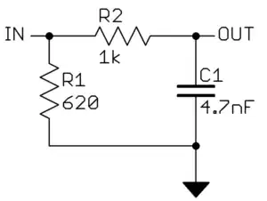
R2 and C1 form a simple low pass filter. The -3dB rolloff frequency of this filter is

f = 1 / 2 * Pi * R * C = 34 kHz

However, that assumes the input voltage has zero impedance. Any impedance of the input source will be effectively added to the R in the forumula above and lower the filter rolloff frequency. If you know the guitar pickup impedance, then you can adjust R2 or C1 accordingly. You want to make the rolloff at least 20 kHz, but still low enough to usefully attenuate the unwanted high frequencies.

Many audio pickups and the like are designed for 600 Ω load. R1 is there to present a reasonable load to the input signal and also to make its impedance somewhat predictable to the R2/C1 filter. You have to check what load your pickups really want. As I said, 600 Ω wouldn't be surprising but it could easily be rather different too. The values in the circuit above are rough examples if indeed the source is around 600 Ω and the input impedance of the amplifier is "high". I'm trying to show you how this filter works so you can adjust it to whatever your conditions really are.

For the circuit above, the signal impedance as seen by the R2/C1 filter can only be from zero to 620 Ω. That gives a -3dB rolloff range of 21-34 kHz, which should be good enough. Note that if the actual source impedance is really much higher than 620 Ω, then R1 will attenuate the signal a lot and you won't get much out. Again, you need to adjust the values to your actual case.

Olin Lathrop
  • 310,974
  • 36
  • 428
  • 915
  • 1
    Electric guitars want to see a >1 MΩ load. 600 Ω would be wayyyy too low. Definitely not what they're designed for. – endolith Nov 09 '11 at 21:41
  • @endolith: As I said, if the source impedance is different you have to change the numbers from the example I gave. That doesn't make the method wrong, just the values I happened to pick for the example inappropriate for this case. Many audio sources do want to see around 600 Ohms load. Apparently guitar pickups are not among these from your information. As I said *"it could easily be rather different too"*. – Olin Lathrop Nov 09 '11 at 22:24
  • I've never heard of any audio device that expects a 600 ohm load. Have you heard of something specific? I know telephones use 600 ohm impedance matching to prevent echos, but nowhere in pro or consumer audio that I'm aware of. – endolith Nov 10 '11 at 03:31
  • @endolith: I've seen 600 Ohm output impedance from dynamic microphones. I thought it's also a common impedance for "line level" audio signals. – Olin Lathrop Nov 10 '11 at 14:29
  • *Output* impedance, sure, but the mic *input* on the mixer will be at least 1.5 kΩ input impedance. I don't know of anything that expects a 600 ohm load. That's a telephony impedance matching thing. http://electronics.stackexchange.com/questions/6846/how-important-is-impedance-matching-in-audio-applications/6854#6854 – endolith Nov 10 '11 at 16:33