4

I have a 9V power supply. I split it in half using a voltage divider buffered through a TL071 op amp. I use the +4.5V rail to power an ATmega328P. The microcontroller has one pin attached to an LED through a 330-ohm resistor.

The problem that I'm having is that whenever the LED is on, the voltage available to the microcontroller on the positive rail drops by about 570mV. The voltage on the negative rail also becomes more negative by 570mV. The voltage across the positive and negative rail remains 9V. It's the virtual ground that's shifting.

I think the reason may be that when the LED is on, the microcontroller+LED draw more current than the op amp can sink (any current drawn from the positive rail must be sunk through the op amp right? no where else for it to go) and so that causes the potential of the virtual ground to rise. Is that what's going on?

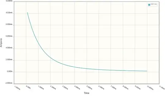
The microcontroller draws 17mA by itself when the LED is off. It outputs about 3.5V (the circuit isn't entirely accurate since it shows the LED being driven from the positive rail; it's actually driven from a microcontroller pin), and the LED requires 1.7V, so that's 1.8V dropped across the 330-ohm resistor, for an additional 5mA or so. I looked at the data sheet for the TL071 but was unable to find any information about how much current it can sink.

Is my understanding correct? How much current can the TL071 virtual ground handle? If the TL071 is the limiting factor, is there another op amp that would do a better job?

schematic

simulate this circuit – Schematic created using CircuitLab

Willis Blackburn
  • 1,217
  • 1
  • 13
  • 24
  • 1
    Skip to pg13 of the datasheet and look at the 'Functional Block Diagram' of the TL07xx. See those resistors between the output stage transistors and the output pin ...? That's what's causing your trouble. TL07xx's just can't source or sink much current. – brhans Mar 01 '16 at 03:32

1 Answers1

5

You certainly have the right idea about your problem. A TL071 is completely inadequate for your purposes. Start with a datasheet. Look at figures 2 and 3, which show how much voltage the chip can put out. Notice that with a load resistor of 10k, you can get about +/- 4.5 volts for a +/- 5 volt supply, but if you drop the load to 2k, you can only get about +/- 3 volts. Your load is the equivalent of about 250 ohms at 4.5 volts, so you'll be in real trouble.

The quickest way around your problem, assuming your schematic is correct, is to boost the op amp current with a transistor, like

schematic

simulate this circuit – Schematic created using CircuitLab EDIT - And a version of the circuit which will handle either type of load is a bit more complicated, but this

schematic

simulate this circuit should work.

WhatRoughBeast
  • 59,978
  • 2
  • 37
  • 97
  • Thanks. I find thinking about the virtual ground confusing because the "output" is 0V. Does the transistor help by providing a lower-impedance path to the negative rail? Does it work the other way or would I need another transistor to handle load on the negative side? – Willis Blackburn Feb 29 '16 at 12:50
  • Also could you explain your choice of PNP for the transistor instead of NPN? – Willis Blackburn Feb 29 '16 at 13:14
  • 1
    @WillisBlackburn - Yes, the transistor provides a lower impedance, which is the same thing as higher current. And the "lower rail" is not useful when thinking about this, since the power supply has + and -, and that is what the circuit is dealing with. And yes, you'd need another if the load could draw from the - rail. Although keep in mind that the virtual ground only has to handle the difference in the two currents. – WhatRoughBeast Feb 29 '16 at 15:39
  • 1
    @WillisBlackburn - Yes, you could use an NPN, but that would be a bad idea. First, you'd need a base resistor, and also possibly an emitter resistor. Second, you'd wind up with a transistor gain of more than 1, and this increased total gain of the op amp/transistor combination would run the risk of instability/oscillation. With the PNP configured as a voltage follower, none of this matters. – WhatRoughBeast Feb 29 '16 at 15:43
  • 1
    I hooked this up tonight and it worked perfectly! Thank you! – Willis Blackburn Mar 01 '16 at 03:49
  • Sorry, one more question about using a second transistor for the negative side. If I think of the PNP transistor in your schematic as being a variable resistor, then I imagine that what the op amp is doing is adjusting that resistor to perfectly match the resistance of the load, leaving the virtual ground centered at 0V. But I can't imagine how it would work with two transistors. Could they both be adjusted in unison or would there need to be a second op amp too? – Willis Blackburn Mar 01 '16 at 04:01
  • @WillisBlackburn - See edit. – WhatRoughBeast Mar 01 '16 at 04:55
  • Thanks! This looks very elegant. Something occurred to me though. I mentioned that in your first schematic the transistor was acting as a variable resistor controlled by the op amp to match the load. Since I know the mircocontroller at least is about 264 ohms, would it not be simpler to add an actual resistor (220 or 330) between virtual ground and negative rail to dump the current from the microcontroller? Then the op amp can handle transient extra current like the LED. Seems like it would work if load was unbalanced but fairly stable. – Willis Blackburn Mar 02 '16 at 04:36
  • @WillisBlackburn - Yup. As long as you trust that the load will never change. Your call. – WhatRoughBeast Mar 02 '16 at 04:39