9

I am trying to build a small battery powered device containing a servo. I would like to be able to turn off the servo to save battery life. I have read previously that MOSFETs can be used to do this, but I am having trouble finding example circuits that are detailed enough (missing resistor values with no way to calculate them) and to be honest I am not too sure what sort of circuit I am looking for (I have never used any FETs before). Can someone please give me a nudge in the right direction?

potentially relevant info:

  • code running on a mega88 @ 3.3V
  • 4.8-6V servo connected straight into the 6V battery pack (I would like to change this)
stevenvh
  • 145,145
  • 21
  • 455
  • 667
jeremy
  • 5,055
  • 5
  • 33
  • 32
  • 4
    Providing the example circuit, even it lacks values, might help. – Brian Carlton Apr 12 '10 at 13:29
  • If you want practical guidance, including part selection, look at some of the speed control projects for R/C systems which have been published - preferably a recent one. A FET that can run the drive motor should have little trouble with a servo. One thing to think about is if you could get away with using an N-channel device to switch the low side as those are fundamentally better than the P-channel devices. However, the brushless motor controllers that are all over the place today use both, so you could pick a P-channel device and drive circuit from there for high side switching. – Chris Stratton Aug 01 '12 at 14:56

2 Answers2

11

You didn't mention how much current you require. Here is a quick guide --

For most switching applications the important parameters are the voltage rating (BVdss), the maximum drain current (Id(on)) and the gate turn-on voltage.

For a 6V battery you want a breakdown voltage at least 6V. Make this a bit higher in case switching produces transient voltages. Since the majority of FETs have voltages of 20V or greater this should not be a problem. Choose a 20V or 30V FET.

Choose a maximum drain current above what the servo requires. The maximum drain current is usually limited by the thermal performance of the system not the device. How much current do you need? How large a device can you use? Do you have room for a heatsink?

To use the FET as a switch in a 3.3V system you want a logic level device. This will insure that the device is fully on (lowest on resistance) at 3.3V levels.

For circuitry I will usually put a pull-down resistor on the gate so that the gate is never floating. For some applications I will place a zener diode across the gate for transient protection.

Daniel Grillo
  • 7,659
  • 18
  • 51
  • 69
jluciani
  • 11,646
  • 1
  • 34
  • 54
  • It is also good design to have a gate resistor to limit the current to the gate. –  Apr 12 '10 at 13:51
  • Not usually. Limiting the current to the gate slows the charging of the input capacitance (Ciss). This increases the switching losses since the FET now takes longer to switch. The higher the voltage you have to switch the worse the losses are. Also the higher your switching frequency is the worse your losses are since you are switching more per unit time. – jluciani Apr 12 '10 at 16:35
  • The application doesn't seem to have high speed needs, only an on/off feature to save battery. I would recommend the series resistor, especially if it is driven directly by the processor. Additionally, once you etch the board it is much easier to put a low value resistor if there are speed issues than trying to add one if the current spike is causing other problems (disturbances to analog circuitry, unexpected resets, etc.). – apalopohapa Apr 12 '10 at 18:10
  • 1
    @Henrik, @jluciani: gate resistor is not for limiting current to the gate, per se (which you don't want to do). It's for several other reasons: controlling the turnon/turnoff time (resistor in parallel w/ diode allows turnoff to be faster), preventing ultrahigh-frequency oscillations due to device gain and device lead inductance, and isolating faults from propagating to the circuit that drives it (esp. if directly from a microcontroller pin). – Jason S May 18 '10 at 12:43
  • A 50-200 ohm resistor usually suffices, you don't want one that is significantly larger. – Jason S May 18 '10 at 12:44
  • @jluciani "the important parameters are the voltage rating(BVdss), the maximum drain current (Id(on)) and the gate turn-on voltage." i identified these values on my datasheet for the Mosfet(IRLB8743PBF) I use...but what is the identifier for the energy consumption of the mosfet itself or is it neglible little?? – Sathees Aug 13 '15 at 18:39
5

You might not need a MOSFET. You should measure how much current your servo uses when you are not sending any pulses on the signal line. I imagine that a well-designed servo would go in to a deep sleep mode and only use a few hundred micro-amps, but I've never tried this.

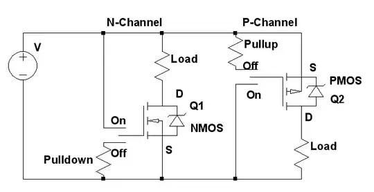
If you do need a MOSFET, I recommend using a P-channel MOSFET on the power line of the servo (the middle wire). You can connect the gate of of the MOSFET to the power supply through a 10-100kOhm pull-up resistor to guarantee that it is off by default. Then use a microcontroller IO line to pull the gate low when you want the servo to be powered, and then make the IO line be a high impedance input when you want to cut servo power.

Your circuit diagram should look like the right-hand side of this diagram from reemrevnivek (just look at Q2) Diagram of how to use MOSFETs from reemrevnivek:

In this case, the "load" on the right-hand side is your servo.

You'll want to look at your MOSFETs datasheet to make sure that the leakage currents are not too bad.

DavidEGrayson
  • 289
  • 2
  • 6
  • 1
    Anyone who upvotes my answer should upvote reemrevnivek for making this diagram! http://electronics.stackexchange.com/questions/3599/basic-p-type-mosfet-question/3604#3604 – DavidEGrayson Oct 23 '10 at 21:25
  • 1
    Servo may be inductive, so you should add diodes to protect the MOSFETs – Jason S Oct 24 '10 at 13:52
  • I always use these: http://www.physics.udel.edu/~watson/scen103/mos4.html http://www.physics.udel.edu/~watson/scen103/mos5.html – endolith Oct 24 '10 at 14:00
  • Thanks for the upvotes, but the diagram was the work of two minutes in LTSpice. Which, by the way, would be a great tool to help simulate this problem. Also, the link points to my answer for questions about the basics of using a MOSFET, which might be relevant. Jason is right, this was a generic diagram, and didn't consider highly inductive loads like servos. – Kevin Vermeer Oct 24 '10 at 22:49