3

I want to provide a fairly constant current (say 10mA RMS, peak 20mA, of 60Hz AC, using a 120V supply) to a load of highly variable resistance. It doesn't have to be super-clean or precise, but should be able to adjust within a few cycles and never stray more than 100% from set current level.

The contemplated load is an electrolytic chemical reactor. It'll be a lot easier to tell once I can feed some current through actual reagents, but best guess right now is that resistance can vary from single-digit to thousands of ohms depending on all sorts of things (temperature, reagent phase, etc.). So I'll want to pick a current and be able to hold that relatively constant as all the other internal and external parameters vary.

What components or circuits can accomplish this?

Transistor
  • 168,990
  • 12
  • 186
  • 385
feetwet
  • 2,322
  • 9
  • 31
  • 55
  • Never straying more than 100% sounds like a fairly loose tolerance! – Neil_UK Feb 23 '16 at 19:43
  • @Neil_UK - Yep, starting easy. I am just curious about the elementary case and didn't want to get distracted with signal conditioning. – feetwet Feb 23 '16 at 19:56
  • So then for your example of 10mA with 100% tolerance, anything from 0mA to 20mA would be acceptable? – brhans Feb 23 '16 at 20:01
  • An AC current is **by definition** not constant. Unless you mean that you want to keep the Peak or RMS value constant. What will be the maximum peak voltage across the load ? Does it need to be mains isolated ? 100% tolerance is silly, just say 10% or so or 1%. These details can have a lot of influence on what kind of circuit is needed. Making a proper specification requires intricate knowledge :-) – Bimpelrekkie Feb 23 '16 at 20:07
  • 1
    What you describe *could* be made with a mains transformer, transform the 120V AC up to a very high voltage (1000 V perhaps), place a high-power resistor in series with the 1000 V to limit the current to 10 mA RMS. Yes crude, dangerous as well, but theoretically it could fit what you describe. – Bimpelrekkie Feb 23 '16 at 20:10
  • What device is the load? – Andrew Morton Feb 23 '16 at 20:12
  • What is the resistance range for the load? – Tut Feb 23 '16 at 20:32
  • @FakeMoustache - right, I'm just looking for relatively constant peak and RMS current. (I like your crude proposal, too!) The contemplated load is an electrolytic chemical reactor. It'll be a lot easier to tell once I can feed some current through actual reagents, but best guess right now is that resistance can vary from single-digit to thousands of ohms depending on all sorts of things (temperature, reagent phase, etc.). So I'll want to pick a current and be able to hold that relatively constant as all the other internal and external parameters vary. – feetwet Feb 23 '16 at 21:19
  • @brhans - Exactly, for a few cycles that variation would be fine. But it should revert to the rough set RMS current after a few cycles. – feetwet Feb 23 '16 at 21:25
  • 2
    @Eugene Sh., Daniel Grillo, Tom Carpenter, nidhin, Peter Smith: Why was this put on hold as unclear when all the additional information was in the comments and I had provided a full solution which seemed to meet the OP's requirements? – Transistor Feb 25 '16 at 10:56

2 Answers2

2

A DC constant current source

This answer is based on a simple op-amp DC constant-current configuration.

schematic

simulate this circuit – Schematic created using CircuitLab

Figure 1. DC constant-current amplifier.

  • Set the wiper on VR1 to give 2 V.
  • OA1 output will quickly rise, turning on Q1, causing current to flow through the load, Q1 and R1.
  • When the voltage on R1 rises to 2 V the circuit will stabilise.
  • At this point the current through R1 = 2 / 100 = 20 mA so we have made a variable current source and the control voltage gives 10 mA/V on the output.
  • In practice R1 is measuring both the load current and the base current so there is a little error.

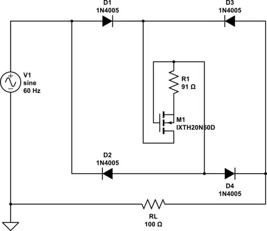
An AC constant current source

10 mA at 120 V is only 1.2 W. An audio amplifer should be able to drive a transformer to achieve what you require.

schematic

simulate this circuit

Figure 2. Constant current inverter.

This is only a rough sketch but may get you on your way.

  • XFMR1 gives a 6 Vrms sine-wave to the power amplifier chip wired as a unity gain buffer.
  • The power amplifier output drives a step-up transformer.
  • R3 in the output completes the amplifier feedback circuit. With 600R shunt 6 Vrms feedback will be generated at 10 mA.
  • It would probably be a good idea to add overvoltage / spike protection on the feedback circuit in case of transients from the transformer. A 1k resistor and a pair of diodes to each power rail might do the trick.
  • R2 is intended to limit the current into the amplifier in the event of XFMR1 powering up before the amp.

Comments on stability, etc., are welcome.

Full circuit

schematic

simulate this circuit

Figure 3. Full (untested) circuit.

  • XFMR1 upgraded to 12 V to power rest of circuit using D1, C1, D2, C2. No voltage regulation is required as we are not too worried about noise.
  • R2, VR1 form an adjustable voltage reference between 0 and 6 V rms. C3 helps take out any high-frequency noise from XFMR1 as this may cause problems with XFMR2 and the feedback loop.
  • Note the 'dot' convention on the output transformer. You won't have dots on your transformer so you may have to invert polarity.

Search for a high-powered op-amp to do the job.

Low-voltage AC constant-current source

This section is to aid understanding of the feedback circuit.

schematic

simulate this circuit

Figure 4. Simple, transformer-less AC constant-current source.

The circuit shown in Figure 4 leaves out all but the essential components for the variable AC CC supply.

Transistor
  • 168,990
  • 12
  • 186
  • 385
  • Very cool -- as far as I can tell (which is little). Now this may be obvious to an EE, but does the amp in this circuit require its own split DC power supply, or is there some clever way of tapping off the low-voltage AC? And do you really mean to feed the *120V* output *before* R3 back into the amp, or is that supposed to be the 6V output? – feetwet Feb 24 '16 at 20:33
  • 1
    (1) Yes, it does require a split power supply as an alternating voltage is required to drive the transformer. (2) Yes, we could be clever and generate the spit supply from XFMR1 if we use a 120:12 V unit. We would then feed the amp input from a 2:1 divider to give us the 6 V. (3) The feedback method suggested is a "low-side" current shunt. We're measuring the voltage drop on R3 caused by the current flowing in the secondary loop. The amp adjusts its output until the voltage on R3 = the + input voltage and this occurs when you've got 10 mA (rms) through R3 (and the secondary). More later. – Transistor Feb 24 '16 at 23:49
  • I've been reading up and beginning to understand this a little better. I would like to actually build this, but without a complete (and correct) diagram I'm pretty sure I'll mess up whatever is "left to the reader!" (For anyone else looking into this, related posts here include http://electronics.stackexchange.com/q/177092, http://electronics.stackexchange.com/q/129609, http://electronics.stackexchange.com/q/23919, http://electronics.stackexchange.com/q/169718. And [the LM317 appears to be a popular component for this sort of thing](http://electronics.stackexchange.com/q/196017/39511). – feetwet Feb 25 '16 at 00:58
  • Answer updated. – Transistor Feb 25 '16 at 10:44
  • Thank you for this! I'm searching for a suitable op amp. Regarding your circuit: I still don't understand how the "low-side current shunt" works as wired: The op-amp never sees the voltage drop through R3. So if the Iout (load) resistance gets really low it could see 120V in the limit? Or do the dynamics of the system prevent that? – feetwet Feb 25 '16 at 22:17
  • (1) Sure the op-amp sees the voltage drop across R3: it's inverting input is connected to it. The op-amp output will increase until the '-' input = '+' input. (2) Opposite to what you think: if the load resistance gets low then a low output voltage will drive the current. If load resistance gets high then we need a high output voltage to push the 10 mA through. Make sure you understand the DC (Figure 1) version. Then have a look at Figure 4 which I'll add shortly. Then ask more questions! – Transistor Feb 25 '16 at 22:31
  • I guess R3 is putting "back-pressure" on the current in the loaded loop? I was thinking: *If I put my multimeter "upstream" of R3, then the voltage to ground will be 600 times higher.* But, the op-amp doesn't see the ground; it only sees the voltage drop across the load, right? So the starting condition is 0V output. The op-amp begins to increase that until the '-' side sees (say) V+ = 6V. With no load, I = V+ / R3 = 6/600 = 10mA. And as we add load resistance *L*, *Vout* increases so the voltage drop (*I L*) across it satisfies *Vout - I * L = V+*. E.g., 10V - 10ma * 400 ohms = 6V. – feetwet Feb 26 '16 at 01:10
1

The simplest way to build an active AC constant-current source takes only 4 parts:

  • A suitably rated bridge rectifier (600PIV, 1A works)
  • A suitable resistor (you'll have to try several values)
  • A HV depletion MOSFET such as the IXTH20N50D
  • And a bit of heatsinking -- the FET dissipates a fair bit of power

Theory of operation: This is your standard JFET constant current source, just bigger thanks to the power depletion MOSFET. AC operation is provided by connecting it to the DC terminals of a bridge rectifier. (RL is a sample load -- whatever load you wish just connects in series, the circuit is insensitive to load position and polarity.)

schematic

simulate this circuit – Schematic created using CircuitLab

ThreePhaseEel
  • 8,858
  • 4
  • 26
  • 41
  • That's nice and simple. I presume it will give a squarish wave output rather than a sinusoidal one as it's basically a DC constant current source inside a bridge rectifier. That's probably fine for the application - I doubt the chemicals will notice. – Transistor Feb 27 '16 at 22:34
  • @transistor -- yeah, the output does come out a bit squarish, which might not be the kindest thing on the grid, but for an odd-off like this, it's no big deal. – ThreePhaseEel Feb 27 '16 at 22:57
  • Yes, for this application "squarish" voltage should be fine so long as it's net-zero and running at least ~60Hz. And not a big deal either, but this is substantially less efficient than the op-amp design because we're cooking off double-digit watts regardless of load, right? Can you clarify the output power type? *As drawn* the load *RL* is getting 60Hz AC? (Sorry, I haven't been playing EE long enough to understand a circuit without some work.) – feetwet Feb 28 '16 at 00:20
  • @feetwet -- the load still gets 60Hz AC, yes -- and the op-amp design has to cook off the power somewhere too – ThreePhaseEel Feb 28 '16 at 00:25
  • Oh, and by the way -- I was off by a factor of 10 on the current *laughs* Let me edit this for you – ThreePhaseEel Feb 28 '16 at 00:30
  • So the scaling here is interesting: To provide constant 100mA we're burning 36W, 10mA is ~7W. What's the functional relationship between current, voltage, and waste energy in this design? (I'll try to work it out myself tomorrow; just thought I'd throw the question out there in case it's trivial for you experienced folks!) – feetwet Feb 28 '16 at 03:06
  • @feetwet -- 10mA is indeed 3.6W -- the 7W rating on the resistor is a derate, basically. – ThreePhaseEel Feb 28 '16 at 05:28
  • BTW -- the general concept here is sound -- I can't get CIrcuitLab to cooperate with the design though (the current source is actually wrong way around atm) – ThreePhaseEel Mar 05 '16 at 04:16
  • Thank goodness LTSpice does this right. Here's a simple DC confirmation circuit using the depletion MOSFET you recommended: http://i.imgur.com/2Zl7qXj.png – feetwet Mar 06 '16 at 22:24