My question is regarding gain and offset of an amplifier.
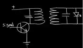
simulate this circuit – Schematic created using CircuitLab
I've used various references however I believe the circuit I want to build is somewhat unique in which I want to convert an input voltage from a sensor which ranges from 2-4 volts. I want to convert the 2-4 volts so that my amplifier output is from 0-10V where 2V corresponds to 0V and 4V corresponds to 10V.
I read through the following post Can someone explain this gain & offset op-amp circuit? and read the famous TI document.
After calculating my "m" (gain) I essentially got m=4.8780 and after calculating my offset "b" I got b=-10.6439.I then proceeded to calculating the necessary resistor values other than Rf which I selected as 51.1k just because I needed to start somewhere in order to proceed with the calculation in this document.
Here's the problem, I'm generating error in my output (i.e. instead of out seeing 10V at the output when 4V is present at the input I receive 13V (that's a 3V diff and a significant error %). How can I remove or remedy this so that I get closer to a 10V output (same goes for 2V input. Instead of seeing 0V I see approx 3V at the output. I can post the math if someone needs to see it however looking at the equation I don't see which of the resistor is actually having a huge effect on this error. How can this be remedied?
Note: On paper the math works out however I'm wondering if Pspice/TINA Ti is having an issue simulating this.
Thanks in advance!