Here's a diagram for impedance:
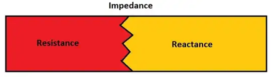
Basically impedance consists of two things: reactance and resistance, making the resistance a subset of impedance.
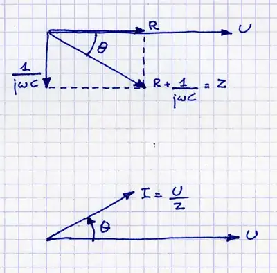
To make the calculations simpler, we use complex numbers to express impedance. This way we can have impedance \$Z=R+jX\$, where \$R\$ is the resistance, \$j\$ is the imaginary number and \$X\$ is the reactance. If we think a bit about complex numbers, we'll see that zero is a valid value for \$X\$. In that case, we only have resistance and no reactance. It's not wrong to say that a purely resistive load has impedance, because impedance consists of resistance and reactance, but it seems that over time the term impedance started to imply that there is some reactance.
Another problem with the term impedance it that it is mostly used for AC circuits and for some reason people usually get exposed to DC circuits first. The reason why impedance isn't used for DC circuits is because of the nature of reactance. Basically for reactance, we have 3 cases: When reactance is zero, when it is positive, and when it is negative.
In cases of positive reactance, we have mostly inductive impedance and the formula for impedance is \$Z=R+j \omega L\$, where \$\omega=2 \pi f\$ is angular frequency and \$L\$ is inductivity of the element. With DC current the frequency is zero and therefore the imaginary part of impedance is zero too, giving us only resistance. Because the resistance is often considerably lower than reactance an ideal coil is considered to have zero resistance and in DC circuits is a short.
In cases of negative reactance, we have mostly capacitive impedance and the formula for impedance is \$Z=R+ \frac{-j}{\omega C}=R-\frac{j}{\omega C}\$. In DC circuits as the frequency approaches zero, the reactance approaches infinity and for that reason ideal capacitors are modeled as open circuit in DC circuits.
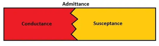
There's also the inverse of impedance called admittance. It's basically \$Y=Z^{-1}=G+jB\$, where \$G=\frac{R}{R^2+X^2}\$ is conductance and \$B=\frac{-X}{R^2+X^2}\$ is susceptance.
UPDATE
Unfortunately, I'm not that advanced so I can't give you a good answer to the update. Basically each part of the circuit acts as a combination of a resistor, inductor and a capacitor.
It is possible to calculate inductance of a piece of wire for example using Biot-Savart law or Gauss's law.
Capacitance among other things may be calculated using Gauss's law for electric field or Coulomb's law. The basic idea is to assume some charge \$Q\$ on the body and using one of the two laws I mentioned to describe an electrical field to get the potential of the body with respect to a point in infinity. After that capacitance can be obtained using formula \$C= \frac{Q}{V}\$.
As far as I know, today there are electronic design programs that are capable of calculating the inductance and capacitance of PCB traces automatically from the PCB layout itself. The laws I provided do work, but to calculate inductance and capacitance of traces on a PCB would be pretty complicated.
UPDATE 2
Reactance can be measured by several types of instruments, depending on the values you expect, the amount of precision you need and what type of instrument is easier to use on a particular circuit.
You can, for example, use a "simple" multimeter to measure capacitance and inductance of a trace. For better results a special type of multimeter called an RLCmeter can be used. It will show exact resistance and reactance at a specified frequency and most better models will be able to display inductance and capacitance. This is handy because in some situations equivalent series resistance of, for example, a capacitor may be important and it cannot be measured with a simple multimeter.
In some cases even an oscilloscope can be used to see the reactance. The reactance will affect signals going through the trace and such effects can be detected with an oscilloscope and then reactance can be determined from effects on the circuit.
As for the intentional part, well the inductance and capacitance are natural phenomena and are unavoidable and will always happen. On some circuits the designer may pay special attention to them, because they can change the way a signal propagates through the trace. This is especially common in modern high frequency digital electronics. On the other hand in some circuits (for example low frequency digital electronics, DC-only systems, etc.) the designer may not need to pay much attention to reactance and can just "let it happen".