7

Following on an earlier question I am looking for a circuit where it powers from USB when it is available and uses the battery when USB is not plugged in.

I want voltage drop to be minimal, zero if possible. So using oring diodes is not possible. The mosfet power oring ICs mentioned in the answer are extremely expensive (4$ for 1K) although they have low voltage drop.

I am looking for a discrete solution where I can build with simple switches or even a cheap LDO. I didn't try to build it but I thought I could use the existence of the Vbus to do a simple switch to control LDO's one from VBus, the other from VBat.

UPDATE

  • Ideally zero drop is wanted however up to 100mV can be tolerated.

  • My system has 4 AA batteries, so there could be cases where the battery voltage is larger than 5V, that is why I focus on the existence of VBus. The small drop comes from the Operation voltage of one of the ICs, it needs to be 3.5V (min) and the larger voltage drop eats into the battery life. (i.e. 4 battery, 0.9 each, 3.6V, 100mV drop, I can squeeze the batteries). If there is a 0.7V drop, I can not use the full battery power. (I have to shut down the system at some point of time to ensure proper operation but batteries has still a lot of juice left)

Frank
  • 2,812
  • 5
  • 30
  • 37
  • eg if Vout is 4.5V - 5V and battery is 4 x AA Alklaine then Battery need a regulator while above 5V and works down to 4.5V + any LDO drop. When Battery ~= 5V when USb is present a simple comparison does not all USB to take over as VUSB < Vbattery.ie system MAY be complex to define. Answer can be simple to implement but not trivial in concept. – Russell McMahon Oct 31 '11 at 04:40
  • 2
    The requirement is easy to meet if you know what it is. ie the question is good but not complete. You say you cannot tolerate a Schottly drop but then talk about LDO's, implying at least some drop. What is the (1) required and (2) (tolerable) output voltage to system eg 5V, 4-5V, 3.3V, 3.3-6V. | What battery is used. Chemistry. number of cells? Will Vbattery be below VUSB when USB is live? Is the battery rechargeable? May or should the USB recharge the battery? Must changeover be continuous or may system "glitch on changeover"? | All those questions affect selecting the best solution. – Russell McMahon Oct 31 '11 at 04:43
  • @RussellMcMahon you may be looking at this the wrong way. My thinking is, if USB present, cut down the battery LDO and feed USB. We can see if USB present via VBus, no voltage comparison needed. Simple on/off. However I am not good enough to draw that circuit, hence the question – Frank Oct 31 '11 at 05:24
  • You MAY be right. I MAY be looking at it the wrong way. But, am I? If you don't know and if you can answer my questions then why no do so. eg What if someone uses a USB supply that has power on the +/- power rails and nothing else (which can happen, regardless of specifications). If you don't care if your device fails when this happens then no problem. If you want it to work as well as possible then knowing as much as possible helps. – Russell McMahon Oct 31 '11 at 07:38
  • I looked again at my questions. Starting at "What is the (1) ..." to " ... changeover" still seem relevant and I'd have thought you could answer out of your head. Your answers may be "don't know" or "don't care" but if you want your need met then we need to know what it is. I can provide a circuit that will do almost anything - as long as I know the specs of "almost anything". – Russell McMahon Oct 31 '11 at 07:39
  • @Russell - The update answers the only questions that seem relevant to me. The specs are to run from USB when it's available, and battery when it's not, with <100mV drop. Knowing *why* doesn't seem necessary in this case. – Kevin Vermeer Oct 31 '11 at 14:16
  • @Frank - Which answer are you referring to? [This answer](http://electronics.stackexchange.com/questions/401/switch-between-5v-power-supplies/807#807), the only one that seemed to reference power muxes, links to the [LTC4412](http://www.linear.com/purchase/LTC4412), $1.59 in qty 100 as well as the $4 Maxim part. There are lots of these ICs, like the TPS2110 series parts that I've used before (also <$2), max input 5.5V) and 316 others from [Digikey](http://search.digikey.com/us/en/cat/integrated-circuits-ics/pmic-or-controllers/2556704). – Kevin Vermeer Oct 31 '11 at 14:20
  • Kevin - " ... to me" - indeed :-). FWIW if 3.5V acceptable then 3.5 / 4 = 0.875 v/cell. Add say 0.4V Schottky drop (could be less) and get 0.975 V/cell. Energy remaining in 0.85 to 0.95 V in a typical Alkaline is a VERY small % of total battery energy. Minutes savings in energy use elsewhere would utterly overwhelm this. eg a buck converter would add little but far more that the above. – Russell McMahon Oct 31 '11 at 15:30

2 Answers2

11

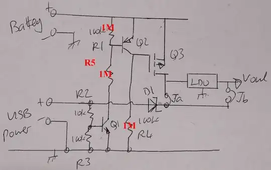
A circuit that will do what is wanted, or as much as what is wanted as has been revealed, is shown below.

This circuit is much simpler than it sounded like it was going to need to be, due to the revelation that the USB power feed could easily accomodate a Schottky "blocking dioe" and still meet the Vout requirement. If this diode had had too high a voltage drop to be acceptable then a circuit withtime delays and current flow direction detection would hav ebeen needed. It can be surprising how much difference a little more information can make to the solution of a problem.


Battery feed at top. USB power feed at bottom.
USB power is fed to load via Schottky diode D1. Power may be fed via Ja and the LDO regulator or via JB as desired.

If feed via JB is used the LDO must survive with external voltage on its output when it has no input. If necessary (depends on LDO) adding another Schottky diode across Ja "pointing upwards" would apply the same voltage across either side of the LDO and minimise quiescent current (in most cases) when USB power is in use.If absolutely necessary another FET could be used to block USB feed from LDO but should not be needed. LDO could be put above Q3 BUT then battery supplies LDO quiescent current at all times = poor.

When USB voltage is absent Q3 = P Channel MOSFET is turned on by R4, feeding battery voltage to LDO and thence to Vout.

When USB voltage is present Q1 is trurned on by R2/R3 and this turns on Q2 (usually held off by R1) which clamps Q3 gate high turning it off, thus disabling battery feed. USB power feeds via D1 either via Ja and LDo or Jb as above.

Battery current when USB connected:

Changed R1, R4, R5 to nominal 1 megohm each to reduce battery load when USB in use. A small MOSFET for Q2 and/or some more thinking will reduce required standby current.

USB on, Q1 on, About 5 uA via R5 to turn Q2 on. About 5 uA via R4 to turn Q3 off. R4 can probably be 10M if slow response OK. ( At R4 = 10 megohm if gate capcitance on Q3 is say 10 nF then time constant for turn on = RC = 1E7 x 10E-9 =~ 0.1 second. Depending on =FET gate threshold it MAY take a few 10ths of a secind for battery to turn on when USB is unplugged. This could dropout powered cct unless a large enough output cap was provided. At R4 = 1m the time constant is about 10 milliseconds and a "usual" sort of cap on output rail would suffice.

Can be "tuned". Q1 on removes voltage from R1. 10 uA quiescent when USB is on =~ 90 mAh/year. This is about 3% of battery pack capacity. Small but annoying.
enter image description here

Q1, Q2 = almost any jellybean bipolar. Q3 = P Channel MOSFET. Vthreshold << Vbattery. D1 = Schottky eg 1N5817. LDO to suit.

Roll your own LDO with MOSFET and eg TLV431 can have about 100 uA quiescent when running and essentially zero dropout voltage. Can be much lower with lower Iq ref diode.

BUT

When you can get eg Microchip's VERY nice TC2104 LDO for under 50 cents in 1's, making your own makes less sense.
ASdded Oct-2001: The TC2104 seems to have vanished. The LM293x series is widely avail;able - see eg Digikeys listings here

Or, here are LDOs with 0.1V or less dropout voltage - Digikey listings quantity 1.


Added 9/2015 Kar asked

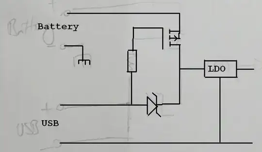
... why are the BJTs needed?
Why not just have a MOSFET and a diode, and that's it?
enter image description here

@Kar Good question.
The MOSFET solution is a good one but it is slightly more design-demanding than may be apparent, whereas the bipolar solution uses a few more components but is easier to ensure operation ioj all conditions.

Tpo use the MOSFET as shown the FET's Vgsth must be chosen to suit.
Battery max voltage (assuming his AA cells are Alkaline) is 1.65V (new cells) x 4 = 6.6V.
In a few cases even maybe 1.655V so say 6.8V for 4.
USB is say 5.3V max when on and 0V when off after any capacitors discharge.
But critical here is not USB Vmax but USB_on_min
USB_on_min = say 4.8V.
Under that condition FET must be off, so
FET Vgs = (6.8-4.8) =~~~~ 2V worst case.
The FET MUST NOT turn on at Vgs = 2V.
Battery min is say 4V and USB low falls to 0V "after a while" so FET must turn on at Vgs = 4V. That puts the FET Vgs_off_max and Vgs_on_min in a fairly narrow 2 to 4V range.
That's certainly doable by correct choice of FET - but datasheet must be chacked to ensure that worst case spread lies in the desired range.
The designer needs to be aware that design is needed!

In the bipolar case the USB Von_min is very easily accommodated by Q1 and if desired full turnoff can occur when V_USB is say 2V so changeover to battery is better defined.
So overall, the bipolar addition adds 2 x Q and 4 x R (small but non trivial) for the sake of better flexibility and designability.
BUT the MOSFET only solution is a good one as long as the complexity that goes along with the simplicity is properly understood.

Russell McMahon
  • 147,325
  • 18
  • 210
  • 386
  • One interesting wrinkle that I don't think your circuit considers is the possibility that VBUS might be present, but not high enough to supply VOUT. Another wrinkle is that if VBATT drops too low, the 'intrinsic' diode in Q3 would conduct current into the battery (bad). Reversing Q3 would mean that if VBATT is more than a diode drop above VBUS, the battery would supply current in preference to the USB. I'm not sure how best to avoid those wrinkles without VBATT having to go through two MOSFETs, or a BJT, or a MOSFET and a diode. – supercat Oct 31 '11 at 20:44
  • On the other hand, if one has an output circuit which won't mind running at a slightly higher voltage when VBUS is present, and one has linear regulators that will simply open-circuit when the output voltage is higher than the regulated voltage, one could simply have one LDO fed by VBUS and another fed by VBATT, and set the VBUS one for a slightly-higher voltage. – supercat Oct 31 '11 at 20:46
  • @supercat - He says Vrequired is a bit over 3.5V and Vbus = USB. Legal USB will always be >>> enough.| Correct - Q3 back conduction an issue but only if Ja used. This needs say Vbat <= about 4.4V. As I noted - a second FET can be added and as easily controlled. Charging Alkaline is more acceptable tham may be imagined :-). | He went out of his way to say he did not want to use a diode in battery cct. I think it would be fine and makes cct trivial.etc – Russell McMahon Nov 01 '11 at 12:54
  • A legal USB device will always supply VBUS when it's active, but I don't think that means that legal devices will always supply either 0 or 5 volts under all conceivable circumstances (including e.g. someone simultaneously plugging three USB-powered keyboard lights into a bus-powered hub along with your device). Further, even if USB-certified devices offered such a guarantee, there are lots of non-USB-certified devices which might be used as power supplies. – supercat Nov 01 '11 at 15:00
  • Incidentally, I wonder how well things would have worked if the standard had permitted things like battery chargers to supply up to an amp at 5.5 volts, and had permitted devices to draw, without negotiation, an amount of current up to (x-5)/0.5 ohms; an attempt to plug two such chargers that wanted an amp each into a supply that could only yield 400mA would cause the voltage to sag to 5.1 volts, with both devices then getting 200mA each. Any idea how well that would have worked? – supercat Nov 01 '11 at 15:06
  • AND somebody may use a lemon with a piece of zinc and a piece of copper :-) - or try to. There is a limit to what you can sensibly design for without specs. WITH specs it's different: (1) Take one **REALLY LARGE** lemon , ... . Latest USB spec is edging towards 1A powering. Latest spec allows dumb hi current USB power sources using shorted data lines as an indication that that's what they are. – Russell McMahon Nov 01 '11 at 19:33
  • My thought is that while it's not necessary to allow a device one is designing to accept power from non-USB-compliant devices, one should at least endeavor to be tolerant of them. For that matter, does the USB spec indicate a minimum fall time in the event that e.g. a self-powered hub loses power? Does it specify that slowly plugging in a connector must never leave it in a state where it would offer significant resistance? I would posit that in such events, a device which has both battery and USB power should be able to switch cleanly between them absent some reason not to. – supercat Nov 01 '11 at 19:40
  • Watch out for voltage drop through large resistors – mcmiln Feb 17 '15 at 20:59
  • @mcmiln - Octarine frog! – Russell McMahon Feb 18 '15 at 03:54
  • 2
    Does USB power feed really accommodate a Schottky blocking diode? If we take 1n5817 as example, it has a voltage drop of 0.45A. Could a high-power device, like a phone, be operated at 4.55V? According to this [paper](http://www.ti.com/lit/an/slyt118/slyt118.pdf), high-power devices need at least 4.75V. – John M. Aug 28 '15 at 05:17
  • @JohnMunroe Your comment is entirely relevant to the general case, but through a process of teeth pulling and fine print reading it became clear that what the OP wanted allowed a diode drop in the USB but not the battery cct. My circuit addresses what he says he wants (see above) but is not ideal if minimum USB voltage drop is wanted. In such cases a second FET in place of D1 would be easily enough added. | From above: He want a minimum of 3.5V but more would be good. He wishes to minimise V drop from batteries so that he can use 4 x AA alkalines. On USB the Schottky drop is acceptable. – Russell McMahon Aug 29 '15 at 15:11
  • 2
    Great answer, Russell. However, why are the BJTs needed? Why not just have a MOSFET and a diode, and that's it? Something like [this](http://tinyurl.com/nbsqqm9) (fixed!) – Kar Sep 04 '15 at 14:35
  • 1
    @Kar Good question. The MOSFET solution is a good one as long as the FTE Vgsth is chosen to suit. Battery max voltage (assuming his AA cells are Alkaline) is 1.65V (new cells) x 4 = 6.6V. In a few cases even maybe 1.655V so say 6.8V. USB is say 5.3V max when on and 0V when off after any capacitors discharge. Critical here is USB_on_low = say 4.8V. Under that condition FET must be off so FET Vgs = (6.8-4.8) =~~~~ 2V worst case. The FET MUST NOT turn on at 2V. Battery min is say 4V and USB low falls to 0V "after a while" so FET must turn on at Vgs = 4V. .... – Russell McMahon Sep 04 '15 at 14:58
  • 1
    .... That puts the FET Vgs_off_max and Vgs_on_min in a fairly narrow 2 to 4V range. That's certainly doable but the designer needs to be aware that design is needed. || In the bipolar case the USB Von_min is very easily accommodated by Q1 and if desired full turnoff can occur when V_USB is say 2V so changeover to battery is better defined. So overall, the bipolar addition adds 2 x Q and 4 x R (non trivial) for the sake of better flexibility and designability. BUT your MOSFET only solution is a good one as long as the complexity that goes along with the simplicity is properly understood. – Russell McMahon Sep 04 '15 at 14:58
  • 1
    @Kar answer added to to reflect your (good) question. – Russell McMahon Sep 04 '15 at 15:13
  • does it really need R1 und R3? Can't they just be shortcutted (removed)? – 2ni Nov 23 '17 at 16:41
  • 1
    @2ni R1 & R3 are added "that thy days may be long on the face of the land". They prevent the related transistors being affected by leakage current when their drive is removed. Long discussions have been held on this subject BUT the reality is that adding them prevents occasional real world spurious turn on issues in some applications. They are cheap insurance against Murphy spoiling your day. | R1 shunts Icb via R4. | When USB voltage is absent R3 shunts current via R2 and reverse bias current via D1. ... – Russell McMahon Nov 27 '17 at 08:20
  • @2ni ... If D1 is a Schottky diode, as it usually will be, then Irvse_D1 can be surprisingly high at room temperature and much worse at elevated temperatures. I suggested a 1N5817 - [**datasheet here**](http://www.mccsemi.com/up_pdf/1N5817-1N5819(DO-41).pdf). You'll see that at rated voltage the max reverse current is 1 mA at 25C !!! and 10 mA at 100C [!!!!!]. Even at lower voltages that's enough to spoil many people's day at typical operating temperatures. No? – Russell McMahon Nov 27 '17 at 08:20
  • @RussellMcMahon got it. The gate should not be floating in case eg no Vusb given. Thanks! – 2ni Nov 28 '17 at 11:48
  • The product linked (TC2104 LDO) doesn’t seem to exist. Is there an alternative you’d recommend? – Volte Oct 21 '21 at 09:53
  • @Volte The TC2104 seems to have vanished in the last 10 years. The nitionally obsolte LM93x series dies a reasonable job - seeDigikey listings [here](https://www.digikey.com/en/products/filter/pmic-voltage-regulators-linear/699?s=N4IgTCBcDaIDYFswE4DMIC6AaEA2KoAlgCZTgAMuArCDgA4AuZAygwE6EB2A5rSAwE86AUzIBDAM4BjEAF9ZQA) – Russell McMahon Oct 21 '21 at 11:33
3

We had a similar problem in a small portable device a while back. We used a battery (CR2032) guaranteed to have a lower voltage than any valid USB power, then used the lowest voltage drop Schottky diode we could find in series with the battery. That was good enough for that case.

In your case it sounds like you can't rely on the battery being lower voltage than the USB power. In the general case, you want to 0-drop diodes, one in series with each power conected. One way to get close to this is to start with two Schottky diodes but put a FET accross each. The diodes will make sure the circuit is powered up as long as one of the voltage sources is on. The circuit can then contain detection of which power is being used and turn on the appropriate FET to short accross that diode. You have to keep monitoring the two input voltages and turn off the FET when things change.

In switching power supplies, this is called synchronous rectification.

Olin Lathrop
  • 310,974
  • 36
  • 428
  • 915
  • I've sketched out a cct but it's an interesting challenge. The Vbattery > to < range adds fun. It actually needs some state memory and time delay and detection of USB depowering if you want to do it well. – Russell McMahon Oct 31 '11 at 15:26
  • @Russell: Yeah, it's not trivial. I would try to make due with low forward drop Schottky diodes, but the OP really seems to want very little drop. – Olin Lathrop Oct 31 '11 at 15:42