2

I'm using an Arduino to control a 12v water pump for a self-watering plant wall. I'd also like to use the same power supply for both, and probably need surge protection of some kind to avoid spikes. I would like to understand the pros and cons in general of various methods of switching power.

I've come across various methods of switch power on and off, but have little idea of the pros/cons for each. Here's the ones I know about:

  • Use a transistor (usually a MOSFET) to switch power.
  • Use an opticoupler to toggle power.
  • Use a relay to control power output. The microcontroller usually doesn't have sufficient power to switch the relay. So you end up having to have an additional circuit which controls power to trigger the relay. This seems silly.

To me, it looks like an opticoupler would be the best option. There's no heat buildup from a transistor (I think), and there's no need to use power to trigger switching the power as in a relay. However, it's not the most common way of switching, and I don't understand why.

If this question is too vague, please do flag it, but also help me make it more concise. I might not know the terminology to ask a good question.

  • 3
    Write your question about a specific problem. Maximize the constraints. – Martin Petrei Feb 05 '16 at 17:51
  • OK I did that @martin-petrei. Thanks. Made it about my specific application, though I'd like to understand the big picture as well. Is this now worthy of an upvote or what would you change? – Burton Kent Feb 05 '16 at 18:23
  • 2
    "it looks like an opticoupler would be the best option. There's no heat buildup from a transistor (I think)" an optocoupler is nothing but a LED and a light sensitive transistor combined. Optocouplers can only switch tens to hundreds of mA at a few tens of volts, so you still need something else (usually a transistor) to switch higher loads. Solid state relays are optocouplers combined with transistors (or triacs) within a single package, and are perhaps the easiest solution. – jms Feb 05 '16 at 22:53

2 Answers2

7

In your case, using a relay to switch the motor is probably the simplest approach. The switching could be done with a FET, but you have to know more about what you're doing and it's not as forgiving.

You are right in that you can't just drive a relay straight from a microcontroller. However, that is still simple to do:

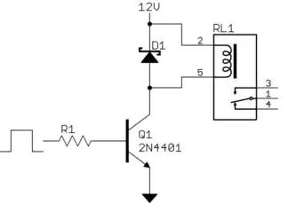
The digital output turns on the transistor, which then turns on the relay. Size R1 to make sure the transistor is saturated when on. Let's say it takes 50 mA to energize the relay, and that the transistor can be counted on to have a gain of at least 50. That means you need a minimum of 1 mA base current. If the digital output goes to 5 V when high, and the B-E drop is 700 mV, then there will be 4.3 V across R1. (4.3 V)/(1 mA) = 4.3 kΩ, which is the largest allowed base resistor. 3 kΩ therefore sounds like a nice value that provides some margin over the minimum required base drive, but would not load a normal digital output. (4.3 V)/(3 kΩ) = 1.4 mA, which just about any digital output can source.

Power connections

I see from the comments that there is some confusion about how all this is powered. The original question was about how to control a 12 V water pump, so 12 V is obviously available. This is also used to power the relay in the circuit above.

The microcontroller probably requires either 5 or 3.3 V. That could be done with a linear regulator from the 12 V, but a buck converter would be better. At these low voltages and probably only a few 100 mA of current, there are plenty of available and cheap options. You can probably find a buck chip with integrated switch and synchronous rectifier, probably even fixed-voltage versions for the 5 or 3.3 V for the micro. All you add is the inductor and some caps, possibly a bootstrap diode, and maybe two resistors to set the output voltage.

A buck converter will waste less power. That may be useful on its own, but the real advantage is in not having to deal with the heat generated by a linear regulator. For example, if the micro and everything around it takes 200 mA, then a linear regulator will dissipate 1.4 W. That's more than a TO-220 package can safely dissipate just in free air. Even a 85% efficient buck regulator would only dissipate 180 mW, which is no problem for something like a SO-8 package the buck probably comes in.

No separate power supplies are needed. Everything can run off the 12 V that is already available. A microcontroller and a relay are a small load compared to a water pump, so this represents only a small additional burden on the 12 V supply.

The real issue is not the supplies but the grounds. In the scenario above, there is only one ground. The ground shown in the schematic above must be the same as the microcontroller ground. Since the pump is running from the same 12 V supply as the relay, the pump must also be connected to this ground.

However, you do have to pay attention to where the return currents flow, particularly those of the pump. The pump should have its own separate ground wire back to the power supply so that the offset voltage generated by its return current times the ground connection impedance doesn't add offset to the micro's ground.

Olin Lathrop
  • 310,974
  • 36
  • 428
  • 915
  • My issue with this is then I need a power input for the arduino, a power input to power the transistor, then power for the actual relay. Would I use the same power supply for all three? – Burton Kent Feb 05 '16 at 20:17
  • Use the same 12V power supply to power the Arduino, the relay circuit above, and your pump. – Steve G Feb 05 '16 at 20:49
  • No you can't connect the 12V directly to the Arduino for VDD. You need typically a LDO regulator from 12V to 3.3V. I highly recommend the circuit that Olin showed, if you want to be even more safe, use an nfet so the arduino is protected by the gate of the nfet. – lucas92 Feb 05 '16 at 21:34
  • @Burt: See addition to my answer. – Olin Lathrop Feb 05 '16 at 22:14
  • @lucas92 Actually you can use 12v with an arduino. Some of them use 3.3v, some use 5v (often from USB), and have built in voltage regulators that can take 7v or more. See: https://www.arduino.cc/en/Products/Compare – Burton Kent Feb 06 '16 at 19:53
  • @OlinLathrop Why a relay though? How is that better than the other options? – Burton Kent Feb 06 '16 at 20:03
  • @Burt: It is simple to understand, forgiving, and robust. To use a FET, for example, would require more expertise that the OP doesn't seem to have. Relays are harder to screw up. – Olin Lathrop Feb 06 '16 at 20:11
2

This question could probably be answered via google or previous posts but I digress.

  1. Mosfets require you to understand how they switch on and off, you have to pay attention to the gate voltage vs the drain voltage or they won't switch, they require very little energy to switch and have high impedance (very low current) inputs. They can also be switched fast. They have a low switching impedance that can get into the milliohm range.
  2. Relays have a coil and require lots of energy to stay in the 'On' (coil on' condition. They are bullet proof for the most part (it takes a lot to mess up the contacts). They are slow (milliseconds) and have switch bounce problems. They also can fail mechanically after millions of switching events. They also have a low impedance and are pretty much a direct connection once switched. Relays have no polarity.
  3. Optocouplers require mA's to 10mA's of current to switch and are moderately fast, use an optocoupler when isolation is required or they can also be used to eliminate voltage translation (All you have to do is turn on an LED.

  4. BJT's are for current switching and have a voltage drop across them and some resistance.

It really depends on your application, if you want to be a good engineer/maker/circuit builder then you need to be able to find out how devices function in a circuit. If you want to switch something on and off but its really up to the REQUIREMENTS of the design what kind of circuit element or switch you will select.

Voltage Spike
  • 75,799
  • 36
  • 80
  • 208
  • Your link isn't as helpful as you seem to think. I've looked and haven't found any summary as good as what you just posted. Thanks! – Burton Kent Feb 06 '16 at 19:57
  • The other answer answers the specific question I had, but I find this more informative, and what I was really trying to find out. I wish I could choose both as the answer. – Burton Kent Feb 07 '16 at 21:23