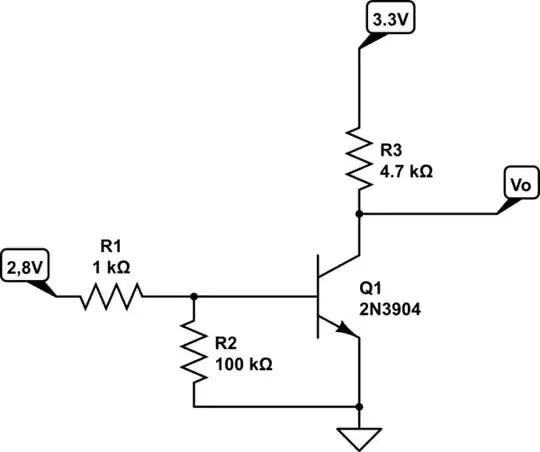
What is the purpose of the resistor \$R_2\$? If I remove \$R_2\$, the circuit will perform the same result, won't it?
simulate this circuit – Schematic created using CircuitLab
What is the purpose of the resistor \$R_2\$? If I remove \$R_2\$, the circuit will perform the same result, won't it?
simulate this circuit – Schematic created using CircuitLab
R2 is used to prevent a floating base. It gives it a defined state, in case the node labeled 2.8V isn't connected. It's a weak pull-down resistor. A floating pin, not pulled to a known state, will act like a mini-antenna, and can float high or low many times and turn the transistor on and off at random.
If that node is driven all the time, either high or low, then R2 is superfluous and can be removed. If the node is connected to for example a microcontroller gpio, that can go High-Impedence/Input (likely at start-up), then R2 keeps the transistor off until the microcontroller goes into output mode.
If the transistor is actually a Mosfet, then R2 is a small drain resistor. Mosfets have a capacitance that may keep it on, if not drained.
Many transistors allow a small amount of leakage current from the collector to the base. If nothing were connected to the base of the transistor, that current could bias the base-emitter junction to 0.7 volts and then get amplified by the transistor, such that the total amount of leakage current sunk to ground would be the emitter-base leakage current multiplied by the transistor's current gain.
Adding R2 provides an alternative path for collector-base leakage; if R2 is small enough that the voltage across it stays below 0.7 volts, current that flows through R2 will still represent leakage from the collector to ground, but it won't be amplified.
In some applications, the amount of leakage current--even amplified--may be small enough not to be objectionable. Adding R2, however, will often cut the leakage current by more than an order of magnitude.
With those nodes at those voltages, you are correct, R2 makes very little difference to how hard Q1 is turned on.
If you replace the R1 drive with 3uA (for instance) instead of 2.8v, the performance is very different.
As an exercise for you, calculate the current required into R1 to
a) start the transistor conducting
b) bring the collector voltage (Vo) down to 1 volt (assuming a current gain of 100)
with R2 present, and with R2 omitted.
R2 at 100K does not affect the circuit to any significance as Neil UK has stated.In fact it could be 10K and things would be fine. R2 does provide a useful function of pull down and should be left in circuit.Consider a high gain transistor and /or a leaky pcb or even mains pickup which is generally electrostatic and therefore of a high impedence nature.