1

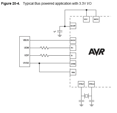
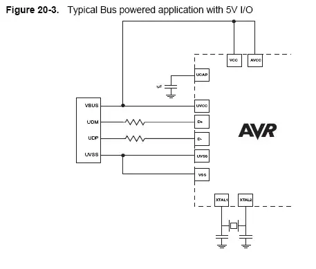
In manual for ATmega32u2, there are two slightly different diagrams for powering the µC via USB. One of them is described as: "with 3.3V I/O", other: "with 5V I/O" (see images below).

For 3.3V, VCC and AVCC are connected (together with UCAP) to decoupling capacitor, while for 5V, they're connected (together with UVCC) to USB's VBUS power line.

Why? How can I decide which configuration to use?

Bus powered application with 3.3V I/O Bus powered application with 5V I/O

akavel
  • 427
  • 1
  • 5
  • 12
  • Are UDM/D+ and UDP/D- wrong in this diagram? It's from the datasheet. The next page of the datasheet (self powered devices) shows these connections the way around you'd expect. – Andrew Apr 11 '16 at 23:07

2 Answers2

1

Use whichever suits your application best (what voltage I/Os do you need?)

I imagine there is an internal 3.3V regulator which takes the 5V VBUS from the USB and regulates to 3.3V, which is then output from UCAP pin and can be used to supply the VCC for 3.3V operation.
For 5V operation the VCC is simply taken directly from the 5V USB VBUS.

Oli Glaser
  • 54,990
  • 3
  • 76
  • 147
1

According to the datasheet for the ATmega32u2, the UCAP pin is the output of the internal 3.3V voltage regulator. Check out the 3rd page for a block diagram and you can see for yourself.

From the diagrams that you posted, one grabs its VCC strait form the USB bus for 5V IO operation while the other connects to the internal 3.3V regulator for 3.3V signaling.

Choosing between which one to use will depend on what you intend to connect to the microcontroller. Other hardware may only do 3.3V signaling for example and will not be tolerant to 5V. Other hardware may only operate with 5V supply and thus maybe output data at 5V.

Be sure to read the datasheets carefully for anything you intend to hook up and that will guide you in what IO voltage to use.

Jon L
  • 4,258
  • 1
  • 22
  • 33
  • So, do I understand correctly: if I connect VCC to VBUS, I'll get 5V power output on all PB0-7, PC0-7, PD0-7 pins? while if I connect VCC to UCAP, I'll get 3.3V power output on all PB0-7, PC0-7, PD0-7 pins? And for input, to have "1" on e.g. PB0, I'll have to set it to 5V in first case, 3.3V in second? – akavel Oct 27 '11 at 19:05
  • @akavel - yes, it sounds like you understand well enough. – Oli Glaser Oct 27 '11 at 22:54