1

I am using the ICL7660 charge pump IC to generate a -5V supply from a +5V. When using the IC on breadboard with a DIP package (ICL7660CPAZ), with two 10µF electrolytic capacitors, it works perfectly fine.

However, when I change the chip in the circuit for the SMD package (ICL7660CBAZ + SOIC to DIP adapter), the output voltage stays 0V or is slightly positive.

I have tried different chips, manufacturers, adapters, capacitors, soldering temperature... SMD components never worked!

Any idea on why the package is changing the behavior of the circuit?

schematic

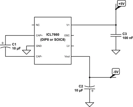
simulate this circuit – Schematic created using CircuitLab

Edesign
  • 448
  • 4
  • 12
  • 2
    How about a nice clear close-up photo of the circuit including top and bottom of each PCB? You're doing something wrong. – Spehro Pefhany Jan 27 '16 at 17:08
  • The +5V comes from a regulator IC (MAX1676), and the -5V is not connected yet. I tried with an other regulator as input, it gave the same result. And you're right, I probably missed something obvious, but I have no idea on what it could be. – Edesign Jan 28 '16 at 08:12
  • Your conclusion could be posted as an answer. You could then accept your own answer. – JRE Feb 24 '16 at 09:23
  • @JRE: good idea, done. – Edesign Feb 24 '16 at 14:05

2 Answers2

2

Apparently, the problem comes from the SOIC to DIP adapter, which adds extra capacitance to the chip pins. I could not find a way to make it work on the breadboard, but it is now working on the PCB (after a proper cleaning with IPA).

Edesign
  • 448
  • 4
  • 12
1

I've used the ICL7660 with electrolyte as well as with modern 'almost zero ESR' ceramic capacitors. Never had an issue.

My gut feeling tells me you're doing small runs at home, otherwise you've probably already debugged with an oscilloscope to pinpoint the problem.

If so, you may want to check for solder bridges between the IC pins and below the components.

Nils Pipenbrinck
  • 5,087
  • 1
  • 19
  • 28
  • I've tried to display signals in oscilloscope, but there's not much to see: only the input voltage and the ground seem to work properly. What could I check on the solder bridges? Continuity? – Edesign Jan 28 '16 at 08:23
  • @Edesign yes, measure resistance between adjecting IC pins and the capacitor pins. If you find anything below 1 Ohm it's likely a short. – Nils Pipenbrinck Jan 28 '16 at 08:28
  • No, all measured resistances are at least a few kOhm. I don't think there is any short in the circuit. – Edesign Jan 28 '16 at 09:00