18

I'm using a couple arduino pro mini's (3.3V) for a home automation project and want to add relays to the final PCB design to switch some stuff on and off.

Since I want to use a 5V relay like this: HF 46F 5V, Miniature HF power relay, 5 V, 1 NO 5 A

I wonder how I can switch this relay with the arduino, since the pro mini only has an output of 3.3V on the pins? The arduino is driven by a 3.7V Li-Ion Battery.

Another question would be how to use the relay safely with high voltages? (apart from trace-width and trace spacing between high and low voltage parts on the pcb) Thanks in advance!

jonk
  • 77,059
  • 6
  • 73
  • 185
Blacky
  • 367
  • 1
  • 4
  • 11
  • 1
    Why not pick a lower voltage relay? There is a 3V version of the model you linked to. You may find that 3.7V is enough to close the contacts on *some* higher voltage relays; it will say in the datasheet. The minimum 'pick-up' voltage for the linked relay is 3.75V, so it would not work. I have no experience of undervolting a relay long term, so I cannot say for definite that you should rely on that technique. – CharlieHanson Jan 23 '16 at 18:41
  • Run the relay from the higher voltage PSU that's feeding the Arduino and take the load off the 3.3 V regulator. You're looking for a MOSFET or transistor switch. There are thousands of posts on this SE site regarding this. – Transistor Jan 23 '16 at 18:43
  • 1
    @CharlieHanson there is no way the controller can source/sink enough current to directly drive a relay like this, even if the coil voltage matches. You'll always need some sort of a buffer stage. – jippie Jan 23 '16 at 18:45
  • @jippie I did not say the controller ever could. As this was a comment and not an answer I didn't see the need to wax lyrical about current issues. – CharlieHanson Jan 23 '16 at 18:54
  • Why is this battery powered and not using a power supply derived from the load supply? Even if you want the MCU battery powered for backup purposes, run your switching element (relay, etc) from a supply derived from the load supply - there's not a lot of benefit to clicking the relay if there's no mains power to run the load, and your battery life will be a lot better if you don't run the relay coil off of it. – Chris Stratton Jan 23 '16 at 20:07
  • @jippie The linked relay requires 40mA @ 5V. 40mA is also, conveniently, the absolute maximum rated current sink/source for the Atmega328P. So I'd say you are wrong; the MCU probably **could** drive such a relay directly. (It would be a bad idea, but that's besides the point here) – marcelm Oct 13 '16 at 07:10
  • @marcelm Check the datasheet for the output voltage that goes with that current. It is possible to use couple GPIO pins in parallel, as long as they are driven at the exact same time. Use of the standard digitalWrite( pin , state ) is not a good idea for that application. – jippie Oct 14 '16 at 04:48
  • @marcelm designing a circuit to use any component at it's absolute maximum rating is not good design practice. (From datasheet: "operation of the device at these or other conditions beyond those indicated in the operational sections of this specification is not implied.") – Tom Carpenter Oct 16 '16 at 11:19
  • Depending on how often you have to energize the coil, you may also want to investigate a latching relay with 3-volt coil (or lower). This one, the [OMRON G5RLU-1A-E DC3](https://www.digikey.com/en/products/detail/omron-electronics-inc-emc-div/G5RLU-1A-E-DC3/4947139), uses 200mA in a short burst to change states from off-to-on or on-to-off, which may allow your Lithium-ion power source to last significantly longer. – MicroservicesOnDDD May 29 '21 at 20:45

3 Answers3

14

The problem is not only related to voltage; but also to current. Basically; the coil operates on a set voltage and requires a set amount of current to be switch on. Commonly, this current to switch on the relay surpasses the maximum power for an output pin.

There are a few ways to control a relay from an Arduino:

  1. You may want to use an Solid State Relay instead, these often can be controlled from 3V to 32V with very low current. Due to the solid state nature of these relays they're also commonly faster, optically isolated, use less power and likely less prone to mechanical failure. You theoretically could dim your lights using one of these relays by turning it on/off fast (PWM signal). But there are better ways to dim lights.

  2. You may want to use an 'Arduino Relay Board' these boards are specifically designed to be ran off an output pin. Do note that some boards are built for 5V and some even require an external 12V input.

  3. You can design a circuit using an MOSFET (and fly back diode) to power the relay directly from the battery and use the output pin of the Arduino for the control signal. (See the other answers) This may not work if the relay requires more power than your battery can provide, in this case you may need an step-up converter to convert your 3,x volt to 12 volt.

  4. You may use other interfacing methods for the relay, for example you could use an IR controlled relay and send IR signals from the Arduino. In this way, power to run the relay is not consumed from your battery. The options are limitless, but you could use RS-232 or even WiFi; though; however those would require an intermediate component to do the translation.

In short; especially since it's an battery powered device; I would suggest using a solid state relay, since these typically require less power.

It's also worth to note that activating the coil of the relay usually continuously draws power (unless if you have a latched relay). So it may be worth to use the relay 'inverted'; to turn something off rather than on; if it's a device that is usually on or to use a latched relay.

Control other devices from an Arduino:

For devices that do not draw a noteworthy amount of current, you may use an 'Logic level converter', typically to interface an 5V Arduino with an 3.3V Arduino.

In some cases it may even work without the logic level converter, but there's no guarantees that it will continue to work if; for example your battery is going low.

Safety:

Your question also included a note about safety, this is actually an entirely different question and too long to fully cover here.

But be sure to use a proper enclosure and it's recommended to optically (and physically, by separating traces) isolate mains voltage from the Arduino. To avoid that failure of a component could lead to your USB becoming mains voltage (110-230VAC).
Paul
  • 875
  • 7
  • 18
  • @jippie You're right, immediately edited it when I saw it. – Paul Jan 23 '16 at 18:52
  • thanks! I think it would be better to use a 3V relay, in this case I don't need the voltage regulator (which takes much space which I don't have).
    I will go with the cheap chinese Songle SRD-03VDC-SL-C (i will only use this for voltages under 20V DC) To drive the Songle relay safely, I need a transistor and a diode (please correct me if I'm wrong) I will go with the NPN 2N2222 and the 1N4007 if that's ok. Here's how my schematics are looking (D5 is Digital arduino pin 5; GND.2 is GND of the arduino): [link](http://i.imgur.com/gr9Psde.png)
    – Blacky Jan 25 '16 at 02:05
  • @Henry I don't know that much of Electronics/schematics, but that's not going to work. You need to put the battery in series with coil, and use the transistor as a "switch". So the Arduino can activate the transistor, and let the higher current of the battery to the heavy lifting. I could check if I can make a schematic, but it'll be tomorrow. – Paul Jan 25 '16 at 02:09
  • yes i realized i mixed something up there :D i googled a bit and ended up with this new wiring: [link](http://oi67.tinypic.com/2uhth5y.jpg) Is it correct? thanks in advance! – Blacky Jan 25 '16 at 02:29
  • @Henry, I was thinking of something like this http://www.wired.com/geekdad/wp-content/uploads/2012/09/relay_driver.jpg just google: "transistor drive relay circuit" you're not the first person to do this, so no need to reinvent the wheel (in this case) :) – Paul Jan 25 '16 at 02:41
  • yes thats the same schematic I drew. I have one more question: I want to add a manual switch to the relay so that I can trigger it manually. Can I just connect the switch like this? --> [http://i.imgur.com/NeDE3sX.png](http://i.imgur.com/NeDE3sX.png) – Blacky Jan 25 '16 at 16:50
  • I tried #5 and they are junk arduino wouldnt make it work. I think the circuit brings the voltage down below 3v I could hear the contacts chatter but wouldnt turn on. –  May 08 '16 at 06:03
  • @Bill, you might have to use a external power supply. To get a little more current available. – Paul May 08 '16 at 11:24
  • This is a useless post; it not only contain glaring errors, it ignores the fact that regardless of 3.3v vs 5v the current for the relay coil must not pass through the MCU. Most practical circuits for driving a 5v coil relay with an NPN transistor or optocoupler will be fine with 3.3v on the *control* side, what is needed is something in the range of 5v on the *coil* supply. – Chris Stratton Oct 12 '16 at 22:58
  • @Chris, I agree that the answer is of low quality. I'll look into editing it (Within 12 jours from now). Thank you for noticing! – Paul Oct 13 '16 at 05:12
  • Suggestion 2 is completely wrong and [has already misled someone into trying to use a logic level converter for unsuitable purposes](https://gathering.tweakers.net/forum/list_messages/2145816). A logic level converter cannot supply the current required to drive a relay coil! Especially the one linked in the answer is limited to (much) less than 1 mA output current (its output impedance is 10 kOhm) and thanks to some conveniently placed body diodes, may fry the connected MCU. – Tom van der Zanden Sep 07 '22 at 22:55
  • @TomvanderZanden I had edited the answer; but didn't remove the old text; which I agree was misleading and not actually an answer to this question. I've rewritten the answer entirely to address this. – Paul Dec 02 '22 at 11:49
3

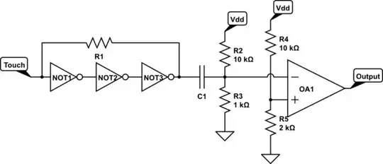
This circuit can solve you problem. I hope it works for 3.3 V supply and 5V relay as well. To explain the reason it works, quote from the linked page:

"This circuit allows a 12v relay to operate on a 6v or 9v supply. Most 12v relays need about 12v to "pull-in" but will "hold" on about 6v. The 220u charges via the 2k2 and bottom diode. When an input above 1.5v is applied to the input of the circuit, both transistors are turned ON and the 5v across the electrolytic causes the negative end of the electro to go below the 0v rail by about 4.5v and this puts about 10v across the relay. "

enter image description here

Abu Bakar
  • 155
  • 8
0

Find a relay that has coil for 3.3volts, or . . .

You are going to need to obtain (or create) a 5 volt supply.

If you search for "step up breakout" you will find products that can step up 3.3v to 5 volts. A device like this will cost a few dollars.

Or, If you are driving AC circuits, you could use a TRIAC driver circuit directly from your 3.3 volts.

An SSR (solid state relay) could also be considered.

EDIT : based upon comments, I just realized you will need a transistor (MOSFET) to drive the coil of the relay.

Marla
  • 5,220
  • 1
  • 22
  • 31
  • Your edit invalidates the whole rest of the answer. Once you have the transistor (actually, better bipolar than FET) the MCU voltage mattes little at least in the 3.3v and up range. – Chris Stratton Oct 12 '16 at 22:59