You are confusing 'inverting' with 'negative feedback'.
Open loop
simulate this circuit – Schematic created using CircuitLab
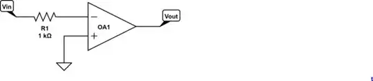
Figure 1: op-amp with open-loop inverting mode.
In Figure 1 the op-amp will amplify the difference between its inputs by the open loop gain. Let's say the open loop gain is 1,000,000 and we apply +1 mV at the '-' input. Since it is higher than the '+' input the output will go to -1 mV x 1000000 = -1000 V. (Obviously on a real op-amp it will stop at the negative supply rail.)
This circuit would not make a good amplifier as the gain would not be controllable, any variation or drift in the input offsets would wreak havoc with the output and any non-linearities of the amplifier would go un-checked. It might, however, make a useable comparitor to detect if the input voltage was above or below, in this case, zero volts.
Negative feedback
Negative feedback occurs when some function of the output of a system,
process, or mechanism is fed back in a manner that tends to reduce the
fluctuations in the output, whether caused by changes in the input or
by other disturbances.
Wikipedia.
Applying negative feedback brings the output under control.
simulate this circuit
Figure 2: inverting op-amp with negative feedback. Figure 3: non-inverting opamp with positive feedback.
Now if we apply negative feedback by putting back R2 the output counters the input. Imagine the operation as a sequence:
- Vin = 0. Vout = 0.
- Vin = 1 V. Vout = 0 at this instant. R1 and R2 form a voltage divider and the '-' input is at 0.5 V.
- Vout starts to swing negative. This pulls the '-' input back towards 0 V.
- The output settles down at Vout = -1 V.
In this configuration the output will move to whatever voltage makes the '-' input the same as the '+' input. This will occur when \$Vout = -Vin \frac {R2}{R1}\$.
Positive feedback
Figure 3 shows the amplifier with positive feedback.
In this situation the scenario will be as follows:
- Vin = 0. Vout = 0.
- Vin = 1mV. Vout still at 0 so '+' input goes to +0.5 mV.
- Vout starts to rise. The '+' input voltage starts to follow it at about half the rate (because of the voltage divider effect).
- Vout hits the + supply rail.
This circuit is often used to make a Schmitt trigger to add some hysteresis so that turn-on and turn-off points are different.
Non-inverting with negative feedback

simulate this circuit
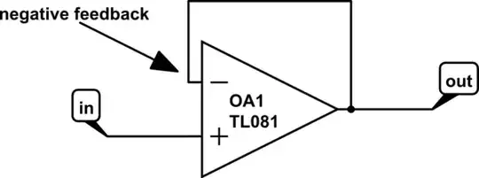
Figure 4. Non-inverting amplifier.
The non-inverting amplifier also uses negative feedback although in a different fashion. I find it most useful to think that the op-amp is 'happy' or stable when both inputs are at the some potential. In this case it's when \$Vout = Vin \frac {R1 + R2}{R1} = Vin (1 + \frac {R2}{R1}) \$.
