You can convert a voltage signal to a resistance in many ways. But first I need to pre-amble this a bit with a few notices.
First: Do as Jasen asks you to do: Attach some resistors in sensible values and see what happens. It is entirely possible your device senses the resistance by sending a small current and measuring the voltage. It would not surprise me if the voltages it looks for on one of the ranges happens to come very close to what your sonar thing actually outputs. In which case you only need to measure the current it sends and make a voltage-follower with enough output power to buffer that current away.
At 50mA the low resistance range would match the maximum voltage almost exactly.
Before you do anything electronic at all, you need to be fully aware that making something for a 12V plug-pack that works and lasts is a whole different story than making the same for a dirty 12 to 14V inside a motorcycle or car. Automotive power has messy spikes and load dumps and for official use the electronics even need to be able to handle negative voltage spikes, because with all that wiring and inductance and heavy loads, that could happen.
Apart from that it's also important to know that the effects those things have will vary between types of electronics, so the protections needed will also vary. Unless you know what you're doing, or the explanations make you confident enough about it, it may not be wise to copy-paste parts of solutions together.
If you want to do it digitally, you can use digital pots, multiplexers with resistors, etc. Digitally has the advantage of allowing you to input a curve, in the case the scale isn't linear, or has an offset, or the expected resistance scale isn't linear, or even both.
I prefer to always see if I can't just turn the one signal into the other with a linear analogue system and see if it needs tweaking for non-linear curves to get it to my liking. Not because digital is boring or too easy, but because there is an elegance to doing it analogue. And of course, because analogue will actually translate an immense number of different voltages compared to the discrete nature of digital.
Be smart
Do you need a resistor?
No.
Because the instrumentation panel will only measure it with either a fixed current and see what the voltage is, or a fixed voltage and see what the current is. The first option is most likely in almost all systems.
So again: Do finally as Jasen asks and measure that shit.
You can model a variable programmable resistance in analogue electronics with a control voltage input using, top of my head, two op-amps a MOSFET a low-value known resistor and about 6 other high value resistors and a capacitor or two for stability. But you don't want to.
If the panel uses a fixed current, you just need to make a voltage buffer or amplifier that can take up that current and amplify to the right voltage, according to:
R = V/I - Ohm's Law.
Or alternatively put:
V = I * R or I = V / R
That should be simple enough, assuming a common ground on your sender it could look like this:
simulate this circuit – Schematic created using CircuitLab
The amplifier can be adjusted, if you double R3 or half R4 it will turn into a factor 3 amplifier, if you double R4 or half R3 it will turn into a 1.5 times amplifier.
What you need to note is that the output can't become all the way 0V, because the transistor will add about 0.8V or so to the signal output, even if the input is 0V, but I fully suspect your system will show full before that voltage if it uses fixed current.
You will need a rail-to-rail op-amp to get this working reliably for most ranges of voltages.
Did I re-affirm you should measure what your system does? Just to be sure, I thought I'd ask.
If it uses fixed voltage, highly unlikely, but if, you need to make a voltage controlled current source, fitting the Resistance formula above for your specific situation:
simulate this circuit
R1 needs to be small, or else the system can never "show" 10 Ohm on its sender lead.
The effect of the above is that the voltage across R1 will cause a current, fitting Ohm's Law, so you can use one of the formula's above to calculate that. The R2 and R3 divide the input voltage to attenuate it according to the formula:
V-Op-Amp-In = (R2 / (R2 + R3))
Which in this case is (10k / (10k + 10k)) = 10k / 20k = 0.5 times.
This voltage is forced across the resistor R1 to cause the current.
Since you still haven't measured anything yet, I cannot help you any further in getting the right values or the right choice between voltage or current system.
If you use an analogue system the protection is relatively easy, as long as your op-amps can handle a small bump in supply voltage (so take some that will handle 20V or more):
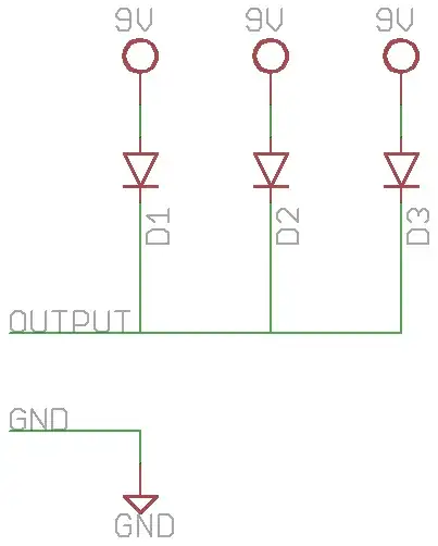
simulate this circuit
The zener or TVS (TVS is better, but a standard Zener could well be enough). Make sure the TVS or zener voltage is at least a few volts below the maximum voltage of the op-amp, but at very least 16V, so that it doesn't trip at a small wobble up to 15.5V on the supply. Those happen regularly when your battery gets old or has a slightly bad contact.
The resistor takes out some of the punch of the spikes. If your op-amps use 10mA it will only take away 0.1V from the supply, so that's fine. In fact, with 10mA for the system, it's possible 100 Ohm would be fine, depending on what output voltages you need.
The two capacitors are there to smooth out dips in the supply voltage.
The diode is a small signal diode, suitable for no more than 100mA, but most op-amp circuits use much less than that. The diode protects from the system draining the caps when the voltage dips. If the system can drain the caps in voltage dips, they have no point.