5

So sharptooth has a question up for creating cheap charger units that uses battery packs to charge a phone:

Is designing and producing a dirt cheap charger really that hard?

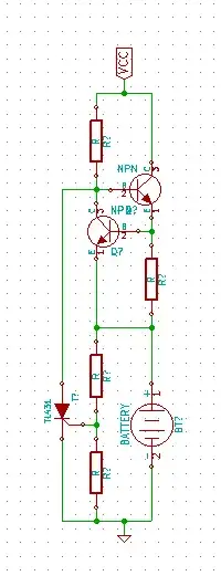
My question is the other way round, how would you design a cheap NiCad charger with the only requirements being that it shouldn't damange your batteries even if left in the charger for extended periods and that it should be as cheap as possible. Here's my shot at it:

Cheap NiCad Charger

It's a simple current limit with diodes in parallel to the battery to protect against overvoltage by bleeding off current when the voltages reaches around 1.4V. (i.e, single NiCad)


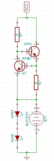
I've added Russell's ideas to the mix and came up with the following, doubt you can go cheaper than this, it meets all the requirements and can be powered from just about anything as well as turning off when the batteries (two or more in series) reached the set threshold. The only way to go cheaper I would guess is to use a constant voltage scheme instead but I'm guessing this will kill your battery a lot quicker, can anyone comment on charging NiCad using constant voltage?

Revision2

s3c
  • 2,525
  • 2
  • 21
  • 31
  • Re comment on my answer. NO! - the added precision is not nice, it's utterly essntial if you want to charge near fully but not overcharge. Modern NimH (although you did say NiCd) are very intolerant of trickle charge. VERY. They must be charge terminated when about charged. Of you use a zener or diode clamp it must be set so it takes almost all the current at Vmax. To do this it must take much of the current at much lower voltages due to the soft knee and the charger will be very very slo to complete the charge. – Russell McMahon Oct 24 '11 at 15:52
  • NB my circuit was in addition to the current source - not instead of. It replaced your diode clamp. Re qualifications to comment on this - consider this my CV :-). [Roll down](http://public.fotki.com/RussellMc/atw/bogo/sl2africa01/?view=roll#1) – Russell McMahon Oct 24 '11 at 15:54
  • I've never charged a battery in a crude manner like this but trust you are correct about the cutoff, with the diode clamp replaced with your circuit we still need a stable voltage to set the threshold from, we can't simply use a zener since that recreates the problem we're trying to solve. – s3c Oct 24 '11 at 16:05
  • You may misunderstand how the TL431 works. It has an internal reference with accuracy of 0.5%, 1% or 2% available. The resistor ratio sets the amount by which the clamp voltage is higher than the reference. eg if R1 = 20k and R2 = 10k clamp voltage will be (20+10)/10 x 2V5 = 7.5V (or half that for the TL**V**431.| You put that cct in place if your diodes and charge at least 2 cells in series with constant current. You set the threshold to 2 x 1.4 = 2.8V and cells will be bypassed when they reach 2.8V for the pair. Ideally you'd want one clamp per cell but minimum clamp voltage does not allow. – Russell McMahon Oct 24 '11 at 17:43
  • Ahh, you're completely right, I didn't get it, it's a pretty good idea. Thanks for pointing that out. Pulling the base of the upper transistor low is probably a better idea now that I think of it, it allows you to turn off the entire circuit (well close to off I'd suspect) – s3c Oct 24 '11 at 20:00
  • "(two or more in series" - Can you share a 1-cell version? ZXRE060? i didn't understand @RussellMcMahon's comment about " 1.25V Vref cannot provide a low enough clamp voltage for a single cell". – johny why Jun 01 '22 at 15:58
  • 1
    @johnywhy Turning clamp transistor on needs TL431 Cathode voltage of <= Vcell_max -Vbe ~+ 1.45 - 0.6V = 0.85 V. The [datasheet](https://media.digikey.com/pdf/Data%20Sheets/Nexperia/TL431_Family.pdf) says Vcathode can fall to Vref (1.25V). In practice I found you can take it to ALMOST Vref -0.6V (when internal diode conducts) - a marginal condition and not guaranteed by the data sheet. || Using the TL431 as a clamp by itself works well but current is limited by device specs. (100 mA for the example version in datasheet). Clever design with extra biasing of transistor may be possible. – Russell McMahon Jun 02 '22 at 01:34

1 Answers1

3

Your circuit is a step in the right direction.

V per cell of 1.4V is OK - note that this will change somewhat with temperature and also with manufacturer and model. Slightly down is better but will not give 100% capacity BUT prolongs cycle life.

Diodes or zeners do not have sharp enough cutoff "knee" - They will allow charge when they ought not and will discharge the battery when they should be off. The cheap & widely available TL431 shunt regulator and one transistor provides a very sharo edge and can have hysteresis added.
TL431 - 31 cents each in 10's, 8 cents each in 100's in TO92 at Digikey.

Basic circuit - add a resistor between T:431 and transistor base - works as shown but "naughty" Can use a P Channel MOSFET. .

enter image description here

If desired these can be provided across as few as each PAIR of cells in a series string so that cell balance is maintained. Each cell-pair will stop charging at the "correct" point and excess current will be sent 'down the chain' to either other batteries or ground. A PAIR must be used as even the low voltage TLV431 at 1.25V Vref cannot provide a low enough clamp voltage for a single cell :-(. TheTL431 or TLV431 cathode drops to ABOUT a diode drop below Vref at turn on, but my personal experience shows that the circuit is marginal and device dependant at 1.4V. There are lower voltage devices but cost is much higher. eg The ZXRE060 from Zetex is superb but 80 cents in 10's and 41 cents in 100's.

Russell McMahon
  • 147,325
  • 18
  • 210
  • 386
  • The added precision is nice but the circuit requires a relatively stable supply to maintain a stable cutoff, my original circuit overcame this with the adjusting current source and can be powered from just about anything. The power source will up the price a little. – s3c Oct 24 '11 at 15:07
  • @s3c "relatively stable supply"? – johny why Jun 01 '22 at 16:15
  • 1
    @s3c When he wrote that he was not aware that the TL431 had a reasonable accurate internal reference voltage. – Russell McMahon Jun 02 '22 at 01:24