USING A LAPTOP LiIon BATTERY FOR 'OTHER PURPOSES':
- ** *WARNING ** *A Lithium Ion battery is akin to a two ended light sabre.
In the hands of an expert it is a weapon of great power and usefulness.
Handled wrongly it can damage the user and itself.
SUMMARY:
You can use the battery easily as long as Dell have not implemented a "secret" protection system (as on some systems)
An under voltage cutout is essential. I have provided a cheap and simple circuit below.
Run time would be about 40 to 12 hours at 100 to 300 mA. A cheap lead acid alarm battery may be a competitive alternative.
NEVER short the battery or draw above rated current. A super cheap protection means is suggested
The battery is easily able to provide the current that you want.
Using the 4400mAh version and a linear regulator will give about 40 hours at 100 mA and about 12 hours at 300 mA.
Using a switching regulator would increase run time somewhat depending on desired output voltage.
An alternative worth considering is a 12V 7AH "brick" SLA ("sealed lead acid") battery as used in many security alarm systems. These are less energy dense than LiIon but may be available at lower cost
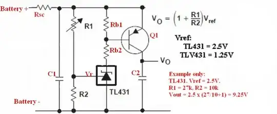
If you use the LiIon battery you will need an under-discharge protector - these can be implemented easily and cheaply. Here is a simple and cheap example which will serve many needs. If I was doing this I may add hysteresis and maybe use an opamp but this will work well.
The TL431 acts like a precision programmable zener diode. It's output voltag is set by R1 & R2. When Vr (at R1/R2 junction) is > 2.5V (the internal reference voltage) then the TL431 conducts cathode to and and turns on Q1. When Vr falls below 2.5V Q1 is turned off. When turned on the voltage at the TL431 cathode is ~- Vref = 2.5V for the TL431 and 1.25V for the TLV431. Dimension Rb accordingly for the transistor used. C1 & C2 are 'sensible values) for the application. 100 uF would usually be fine and much less may be OK. Q1 to suit current, voltage from from battery to load etc. eg a TO92 transistor (eg BC327) would be OK at 50 mA load an 9V out. Above that level a DPak SMD or TO220 with no heatsink would be OK to a few hundred mA.
Q1 can be PNP bipolar or an N Channel MOSFET - I'd probably to use a MOSFET.
- Current when turned off: This circuit draws Vbat/(Rsc + R1 + R2) when turned off. For the example values shown and assuming Rsc=0 then I = say 9V/37k ~= 0.25 mA. This uses 6 mAh/day or ~= 22 mAh/week. In time it too will deplete the battery but it should be OK for a week+ in th present appklication. R1/R2 could be changed to say 270k & 100k to give a drain of under 10 mAh/Month.
Rsc is provided to prevent excessive current being drawn.
For mean currents << Ibtmax then Rsc >= Vbatmax/Ibatmax.
ie shorting to ground after Rsc will not draw excessive curremt.
eg Imax = 4.4A, Vbat max = 3 x 4.2 = 13.2V.
Isc >= 13.2/4.4 = 3 ohms.
Isc will waste energy. At low current << Ibatmax the losses will be OK.
eg at 300 mA, Rsc = 3 ohms.
V_Rsc = I x R = 0.3A x 3 ohms = 0.9V.
Power in Rsc = P_Risc = I^2 x R = 0.3^2 x 3 = 0.27 Watt.
ie using a 3ohm, 1 watt series resistor will protect the battery and it will dissappear in a puff of smoke if you short circuit it to ground (Power = V^2/R = 13.2^2/3 ~~= 50 Watts.
Be CERTAIN that Rsc is the sort that will go open circuit whenover heated.
eg a cheap wire wound resistor will be fine.
You may have trouble getting the battery to deliver power, but probably not. Some manufacturers put security systems in some of their batteries so that an eg laptop must use their battery - and in the process this may make the battery hard to use elsewhere. Dell have done this on some models in the past. You will need to determine if this applies to the 1525 battery.
If you can measure between 9V and 13V on two of the battery terminals it is probably usable. Fully charged = 3 x4.2V ~= 12.6V. Fully discharged to say 3C.cell3x 3V = 9V. As long as you limit discharge to voltages above 3V and NEVER draw more than about 4A from it you should be very safe.
Replacement 1525bateries can be had in 6 cell, 4400 mAh version , for $US45, and 9 cell 6600 mAh version for $53.
Fot the 4400 mAh version (3 cells x 2 strings) the maximum current is probably 4400 mA. The manufacyurer MAY allow up to 2C = 8.8A bit 4.4A is far safer.
For the 6600 mAh version (3 cells x 3 strings) the maximum current is probably 6600 mA. The manufacturer MAY allow up to 2C = 13.2A bit 6.6 A is far safer.
As you can't be sure what capacity you are liable to have generally, limiting to > 4A is wise.
!!! E&OE YMMV DTTAH ...
The above circuit is "out of my head" and I have not tried or simulated it. It is based on the classic TL431 shunt regulator circuit. There is every reason to think it will work OK but please verify for yourself that it meets your needs OK.