I'm trying to repair this battery-powered LED bike light but do not really understand the circuit.

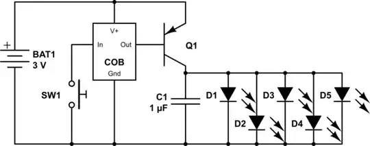
Positive terminal middle left, negative bottom left. Momentary push switch at the top, transistor on the right, capacitor in the middle, 5 LED array at the bottom. The lights are not supposed to blink: just on/off. The switch works, as do the lights (when transistor is shorted). Capacitor seems to work.
- What is likely under the epoxy? Just water resistance for resistors or is it actually a chip? How does this design work? Is there a need for a capacitor in a battery-powered LED circuit?
- I believe the transistor is broken. My diode tester measures 800 ohms from both positive top to middle and positive bottom to middle but also 680 ohms negative top to middle and 1260 ohms negative top to bottom (others are infinite). From this I guess that it is PNP with middle being base. Does this sound correct?
- The part number is S8550 D 331. Only results are Alibaba without data sheets. Close match by name is SS8550 from Fairchild (https://www.fairchildsemi.com/products/discretes/bipolar-transistors/small-signal-bjts/SS8550.html). Dimensions are slightly off. Does this seem a reasonable replacement? Any clue on the differences between models, other than leg spread and ammo vs bulk packaging?