3

I am looking for a simple circuit which can be used to limit the current flowing through a FET. There is a bus line which is pulled up to the battery voltage (12V) by a 510\$\Omega\$ resistor. A FET pulls the line low to transmit a pulse along the bus. In some cases it may be occur that the bus is directly connected to 12V, in which case the current through the FET needs to be limited.

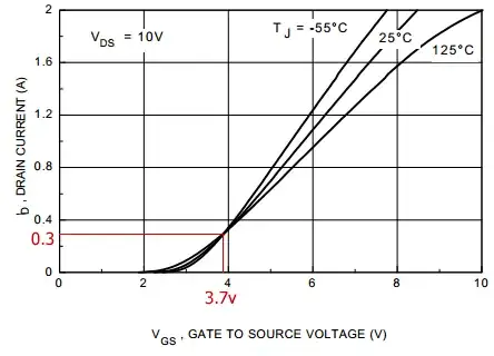
We would probably use a 2n7002 FET, so the current needs to be limited to below 300mA. It does need to be able to sink up to about 200mAThe FET needs to provide a hard pull down, so adding an inline resistor is not an option.

I looked at using current limiting diodes (such as those from Central Semi) which have the perfect type of characteristic, but the current limit is too low.

What options are there which are simple and have a low component count?

stevenvh
  • 145,145
  • 21
  • 455
  • 667
duncan drennan
  • 131
  • 1
  • 4
  • "Current-limiting diodes" are just FETs. "The CLD or constant current diode is basically a junction FET transistor operating with its gate shorted to the source terminal" – endolith Oct 19 '11 at 21:31
  • If you're planning to sink 200mA, the 2N7002 is really inadequate. Abs Max is 300 mA, and maximum continuous is 115 mA. – markrages Oct 19 '11 at 23:38
  • You have competing requirements: "hard pull down" and "current limiting". The only way to bring a low impedance source near ground is to sink a lot of current. What is the worst case? I.e.: how close to 0V does the bus need to go, how much current, and for how long? – tyblu Oct 20 '11 at 01:46
  • This sounds like a simple automotive protocol like LIN. Are there no standard driver ICs for this? – starblue Oct 20 '11 at 06:42
  • @starblue Yes, it is a simple automotive protocol similar to LIN bus. Some vehicles are out of spec in terms of the amount of current that needs to be sunk to pull them low and the standard drivers can't sink that current. The FET is totally adequate in terms of its ability to pull the bus low, but the current limiting aspect is to protect the FET against a fault such as battery being directly connected to the bus. – duncan drennan Oct 21 '11 at 07:44
  • It probably wouldn't be hard to come up with a simple circuit if we knew what the highest allowable voltage is for the bus low state. – Olin Lathrop Apr 11 '12 at 17:16
  • As this is for an automotive comms protocol as you say, have you thought about fault-tolerant CAN? It can handle short-circuits to Vbat or ground and continue communicating – BullBoyShoes Apr 12 '12 at 11:40

2 Answers2

2

Can you use an LM317 voltage regulator configured in current limiting mode? If you can live with the 1.25 volt drop.

SteveR
  • 1,622
  • 9
  • 12
  • 1
    Yeah, limit the bus source. Put it ahead of the 12V regulator (assuming one exists) if the drop is too much. – tyblu Oct 20 '11 at 01:56
  • Yes, and if the bus has higher current loads then branch off with the current regulator to the fet circuit only. Providing the V drop is acceptable. – SteveR Oct 20 '11 at 14:26
  • It might work. I am trying to figure out what kind of voltage that will see across it when the FET is off and how it will need to be protected against transients – duncan drennan Oct 21 '11 at 07:48
2

Why can't the FET do its own current limiting? Isn't a FET basically a voltage to current converter?

Instead of providing 5v (or whatever) to the gate to switch it on, could you use a resistor divider to provide about 3.8v which will automatically limit the current to about 300mA.

3.7v gives 300mA

As stevevh mentioned, there is some variation around this value. You would have to determine how much variation there is, and whether or not this variation causes it do go out of spec.

The variation at 3.7v doesn't seem to be caused by temperature.

Rocketmagnet
  • 26,933
  • 17
  • 92
  • 177
  • What the graph in the [datasheet](http://www.fairchildsemi.com/ds/2N/2N7000.pdf) (fig. 1 on page 4) doesn't say is that there's a lot of variation around these values. You'll need feedback to set the desired current. – stevenvh Apr 11 '12 at 16:44
  • I did wonder, especially about temperature variations for automotive. However, it might be Ok if the variation is still within spec. It would certainly be a cheap solution. – Rocketmagnet Apr 11 '12 at 16:46
  • No, not caused by temperature. It's production variation. You take one FET and it's 300mA at 3.7V, take another one and it's 350mA at 3.7V. The graphs show typical values, variance is hardly ever mentioned. – stevenvh Apr 11 '12 at 16:53
  • Well, he needs between 200mA and 300mA, so it's quite possible that process variation is within that margin. – Rocketmagnet Apr 11 '12 at 16:57
  • No, probably not. Process variation can be quite large. I would assume *at least* a factor of 2 each way, most likely more. Besides, if it's not specified, you can't rely on it. Using a transistor open loop as a current sink is not a good idea. – Olin Lathrop Apr 11 '12 at 17:15