I have a constant current source and analog input channel but it seems I can not directly read rtd as resolution needs mv levels. I cannot use circuit so is there any product or solution help me to read simply using analog input channel range 0-5v or 0-10v. Thanks.
Asked
Active
Viewed 1,908 times
-1
-
2Sure you can directly read it. 1 mA through 100 ohms gives 0.1 volts, and this will change with resistance. Oh, you mean the changes aren't big enough. Why didn't you say so? Please specify temperature range and desired resolution, along with the resolution of the ADC you are using. As it stands the question is unanswerably vague. – WhatRoughBeast Jan 01 '16 at 21:03
-
1What temperature range? Plenty of industrial converters but these may be a bit pricey. Is this hobby? – Transistor Jan 01 '16 at 21:09
-
(1) "*I can not use circuit...*" What *can* you use? (2) What are you ultimately trying to accomplish that's causing such constraints? (3) "*...is there any product...*" Product recommendations are off-topic on EE.SE. (4) Have you done any literature search about RTDs? – Nick Alexeev Jan 01 '16 at 21:11
-
1The "I cannot use circuit" is quite... Limiting. Usual method is either an IC or whetstones bridge into an IC – Jan 01 '16 at 21:16
-
1See [Can't get a precise reading with PT100 temperature sensor](http://electronics.stackexchange.com/questions/93243/cant-get-a-precise-reading-with-pt100-temperature-sensor). – Transistor Jan 01 '16 at 22:53
-
1sounds like you want an *instrumentation amplifier*. – Jasen Слава Україні Jan 01 '16 at 23:11
-
@Jasen Yes. But without using ic like maxim3185 can i use an amplifier if so can you make à suggestion. Thanks. – Soso5 Jan 01 '16 at 23:17
1 Answers
1
You can make a usable amplifier from almost any op amp. In general you can do something like
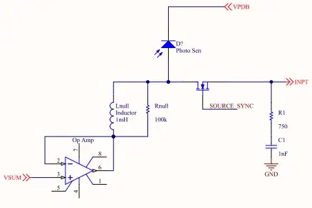
simulate this circuit – Schematic created using CircuitLab
assuming that, having made one current source, you can make another. The op amp has a gain of 125, which will amplify 80 mV (160 - 80) to 10 volts, and offset the output by the equivalent of 80 mV at the input. When you specified 5 mV on a 10 V range, this suggests that you have a 12-bit ADC. The difference in resistance between -50 C and -49 C is 0.41 ohms, which will produce 51.25 millivolts at the output, which suggests an approximate resolution of 0.1 deg C/lsb on the ADC.
Of course, this will not account for the lead resistance on the Pt100, although you can do a first approximation by varying R1. This will produce secondary temperature effects, but given the coarse resolution you've got, you probably won't notice that.
WhatRoughBeast
- 59,978
- 2
- 37
- 97
-
-
@Soso5 - What do you mean by off-the-shelf? What part of the circuit is a problem? The amplifier can be almost any opamp, although you'll need either rail-to-rail with a 12 to 15 volt supply, or a bipolar opamp with +/- 15 volt supplies. – WhatRoughBeast Jan 02 '16 at 15:46
-
@Soso5 - Oh, for Heaven's sake. Just Google on "RTD signal conditioner". Start thinking for yourself. It's a lot quicker than waiting for somebody else to do it for you. – WhatRoughBeast Jan 02 '16 at 17:04
-
@WhatRoughBeast thanks for the effort and advices of course searched before but wanted to get expert advices. – Soso5 Jan 02 '16 at 17:53