5

While I have an assortment of 5V, 9V, 12V wall-warts, but I don't remember ever seeing one that is 18VDC and trying to avoid a trip to specialized parts shop, since I have all other components of a circuit (of a microphone mixer) that I am building.

Here is the circuit in question:

enter image description here

(Source: http://www.aaroncake.net/circuits/mixer2.asp)

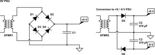
As one can see, it requires +9VDC, -9VDC and GND. I've never built such circuits that have negative potential (I know it is relative). Wondering if someone can help illustrate / explain, if it is possible to power this somehow using a 9VDC wall-wart ?

bdutta74
  • 3,524
  • 11
  • 46
  • 67
  • 2
    Laptop power bricks are often about 18V. – pjc50 Dec 29 '15 at 10:30
  • 2
    Is there a reason you absolutely need DC coupling between stages? Op amp. offset voltage, amplified, can be a pretty annoying drawback that is easily reduced with AC coupling. Also bear in mind the potentiometers will make the input impedance vary, which is not always desired and preferably avoided by placing the cursor to the OP amp side. Otherwise you could always opt for an asymmetrical power supply (say 9V) and a bridged amplification. –  Dec 29 '15 at 10:39
  • @pjc50, great idea. I do have few laptop power bricks that I could scavenge for this project. Simplifies many things. – bdutta74 Dec 29 '15 at 14:13
  • @Nasha, thanks for the suggestion. While I can appreciate the benefit of AC coupling as described, I am not knowledgeable enough in analog electronic circuit design to make the appropriate changes to the circuit. – bdutta74 Dec 29 '15 at 14:19

5 Answers5

14

You will probably find that two 9V wall warts will do the trick - connect the positive output from one to the negative output from another - this connection is the "new" 0V and you'll have +9V and -9V available - regard it as two 9V batteries in series with the middle (common) connection being called 0V.

Because wall warts produce isolated output voltages, they can used like this but always double check with a meter first to ensure everything looks and feels OK.

Looking at your op-amp circuit you should be able to get aways with a single 12V wall wart and a rail splitter made by two resistors across the supply. The junction of those resistors will be 6V up from the negative rail and ALL the points marked with an "earth" symbol on your circuit can connect to this point. This is a much used technique but, as always, it won't suit every target circuit but looking at your circuit it should be OK.

Andy aka
  • 434,556
  • 28
  • 351
  • 777
  • This the kind of trick I was hoping to see. The 12VDC wallwarts are aplenty in my bin and definitely avoids putting two 9VDC wallwarts together, making the circuits larger than it needs to be. – bdutta74 Dec 29 '15 at 10:55
  • Cool. Redraw your circuit with what I've suggested doing and add it to your question as an edit section - just so I can double check. It's easy to get this wrong and lose faith should you forget something! – Andy aka Dec 29 '15 at 11:04
  • 2
    It's a not a virtual ground (despite seeing this term used this way) it's a mid-rail generator. In the OP's circuit there won't be much current injected into the potential divided mid-rail but that depends on the feedback resistors on the three front-end op-amps so a certain care should be taken on this just using a mid-rail voltage divider. This is why I suggested a redraw and re-check. That injetced current can make the mid-rail a little offset from tru mid-rail and noise can also appear on it. Some folk will buffer the mid-rail with a unity-gain op-amp because of this. – Andy aka Dec 29 '15 at 11:53
5

If you have a transformer-based PSU available you can probably convert it from single to split-rail as shown below.

schematic

simulate this circuit – Schematic created using CircuitLab

Note that each rail is now only half-wave rectified so I'd recommend some large caps or voltage regulators to eliminate hum.

If you want to keep a standard jack on the PSU then convert it to an AC PSU by removing the rectifier and capacitors and put the diodes and caps into your project case.

This configuration can also be used to make an 18 V PSU.

schematic

simulate this circuit

Transistor
  • 168,990
  • 12
  • 186
  • 385
3

If you're wanting to produce a split-rail from a single supply, you might find DC-DC inverter ICs useful. Such as these from Microchip:

http://uk.farnell.com/microchip/tc7660hcpa/dc-dc-volt-converter-7660-dip8/dp/9762698

I tried these DC/DC converters in an audio project with single supply limitation (guitar effects pedal) and they worked a treat. Here's an example of a simple audio project that uses the 7660, hopefully it will be of some use to you!

http://www.generalguitargadgets.com/effects-projects/distortion/kc/

Tom Wilson
  • 113
  • 8
  • 1
    For audio applications you might like to look at any noise on the voltage output and follow it with some careful filtering. – David Dec 29 '15 at 10:31
  • Thanks for the answer. It's a great suggestion, and with a useful link there, since I am hoping to make some (DIY) guitar pedals as well. – bdutta74 Dec 29 '15 at 10:56
0

If you still want a dual supply after considering these other great ideas, you could build a simple voltage doubler, either by using a Cockroft-Walton type circuit, or a push-pull supply, with maybe a couple of analog voltage regulators thrown in. The first approach is not a very stiff supply, but is probably adequate for your circuit's load. To get to a split supply from the doubled supply, follow the previous responder's suggestions.
For the second approach, a transformer is needed but something that works is not hard to come up with. Just get a big core (e.g. ferrite cup-core or toroid) and fill it up with trifilar windings (i.e. 3 wires wound together). Pay attention to the phasing, make sure your switching transistors are driven hard enough to saturate, and use the clock frequency to control droop leading to ripple. If you want, you could estimate each winding's inductance from the A(L) value for the core. The output is square-wave a.c., so a split supply is generated by single rectifiers with capacitive filters. Note that there are also IC's made to generate a negative supply directly from the positive supply, by capacitive switching. Using this you would have a split supply right off the bat. I suspect that this approach is also adequate for your circuit's load.

blarz
  • 11
  • 2
0

An option is to use a DC/DC converter. You can use a single +/- DC/DC converter such as XP Power here.

DC/DC converters will have switching frequency noise (10's of mV), so you can use a PI filter coupled with simple linear regulators (+/- 9V), to reduce noise. Select the DC/DC converter based on voltage, current load, switching noise frequency, and power-supply ripple rejection. Set the DC/DC voltage higher than drop out of the linear actuators.

For high precision a good reference design and suitable (TI) chips can be found here.