3

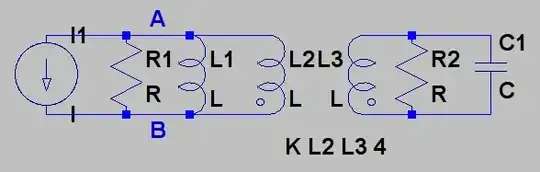
The circuit below contains an AC current source and an ideal transformer along with some passive elements. I marked the points A and B, because I'm trying to find the power dissipated in the terminal A-B.

enter image description here

I could rewrite the circuit using Thévenin's theorem to this kind of circuit, where Z are complex impedances and V is a voltage source, because I feel safer calculating the power dissipation from this kind of source.

enter image description here

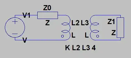
The part of the transformer on the left-hand side could be written as an impedance related to Z1 through \$(N_1/N_0)^2\$

Now, though, my question is: Which power dissipation in this "equivalent" circuit would be equal to the power dissipation over the A-B terminal above?

Karin
  • 307
  • 1
  • 2
  • 12
  • If there's a better way to draw the diagrams, please tell me! – Karin Oct 12 '11 at 20:08
  • 1
    Those are understandable, but the best way is to use your simulation or schematic software to draw it up, take a screenshot, and upload that. See [this question](http://electronics.stackexchange.com/questions/1024/good-tools-for-drawing-schematics) for some example packages. – Kevin Vermeer Oct 12 '11 at 20:24
  • Thanks @Kevin, although I was hoping for a standard ASCII way :) I used "European resistors" for impedances, is that OK? – Karin Oct 12 '11 at 20:40
  • That's perfectly fine! The standard ASCII way would probably be the output of the fascinating [aacircuit](http://www.tech-chat.de/aacircuit.html) (Link is in German but program is internationalized). That program notwithstanding, the current circuit is much more readable than the ASCII version. – Kevin Vermeer Oct 12 '11 at 21:59

1 Answers1

6

Power dissipation is not preserved in Thévenin and Norton equivalent circuits.

For a simple example, consider a 1 volt voltage source with 1 ohm across it. The power dissipation is 1 watt.

But the Thévenin equivalent circuit is just the voltage source by itself. 0 watts.

markrages
  • 19,905
  • 7
  • 59
  • 96
  • 4
    Well, power dissipation through the **load** is preserved. – Ben Voigt Oct 12 '11 at 21:17
  • Are you sure that those circuits are Thévenin equivalent? Your first circuit is `A--V--R--B`, which is already its own Thévenin equivalent. – Karin Oct 12 '11 at 21:18
  • @Karin: The 1 ohm resistor is in parallel, not series. – Ben Voigt Oct 12 '11 at 21:19
  • @mark: Sorry, I should clarify that I want to find the power dissipation when the circuit is under load. – Karin Oct 12 '11 at 21:29
  • For finding the Thévenin at A..B in your first circuit, you cannot combine the resistor and inductor. The resistor is in the source and the inductor is in the load. You need to keep them separate. See Ben's comment. – markrages Oct 12 '11 at 21:35
  • Thank you, now it's clearer. I could still rewrite the left side of A-B as a serial voltage source and resistance, right? And the power dissipation of the A-B terminal would be the power dissipation over the impedance that I can rewrite the right side as? – Karin Oct 12 '11 at 21:42
  • I'm not sure what you mean by the power dissipation of the A-B terminal. The power dissipation in the load (the impedance to the right of A-B) will not change as you transform A-B into Thévenin or Norton equivalents. – markrages Oct 12 '11 at 22:11