17

I'm trying to do find the voltage over R1 in the following circuit, where L1/L2 is an ideal transformer. LTSpice complains that the "Matrix is singular". Why? I've tried to play around with lots of different values in order to see if it's a problem with approximation.

enter image description here

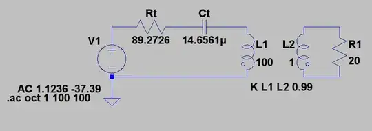
The numbers after "AC" are the max amplitude and phase (in degrees).

Karin
  • 307
  • 1
  • 2
  • 12
  • The analysis works fine if I remove R1 (replacing it with a gap). – Karin Oct 12 '11 at 13:33
  • Can you make L1 and L2 non ideal by a very small amount. Maybe add a milliohm of less. I've had something similar happen a few decades ago :-) – Russell McMahon Oct 12 '11 at 13:51
  • 1
    @RussellMcMahon: I tried to set their "parallell resistances" to 1m, if that's what you meant. It resulted in a current over R1 on the order 10^-10A. – Karin Oct 12 '11 at 14:01
  • Is it working? Did the 10M between ccts make it work? If you emove the 10M does it work? If you add parallel R does it wiorK. What current are you getting / expecting? – Russell McMahon Oct 12 '11 at 15:59

3 Answers3

20

You need a DC path between the two circuits. Put a high value resistor between them, say 10M.

I checked that it worked using Pulsonix (actually SIMetrix) SPICE. I got a singular matrix error without the resistor.

Leon Heller
  • 38,774
  • 2
  • 60
  • 96
  • 11
    or just ground the secondary – endolith Oct 12 '11 at 14:49
  • @endolith: How could grounding both circuits work? There is a difference in potential between all nodes in the circuit as it is designed now. – Karin Oct 12 '11 at 15:07
  • 1
    I considered that, but realised that Karin probably wanted the secondary to be isolated. – Leon Heller Oct 12 '11 at 15:55
  • 8
    @Karin - the secondary has no reference to anything at all as it is now. As shown, in real; life it could be at -10V average relative to ground, or at + 1,000,000 V relative to ground. The maths may have trouble with this lack of definition. The 10Mohm or the ground boty do the sme job of providing a finite connection between the two. – Russell McMahon Oct 12 '11 at 16:05
6

There is a SPICE parameter called RSHUNT which adds shunt resistors to GND on every node. By default it is usually set to ZERO (that meaning no shunt resistors). If you make this a very high value (1e12) then it won't affect the simulation, but it will provide a finite resistance between all nodes, avoiding the singular matrix error.

Brett
  • 61
  • 1
  • 1
  • 3
    This option should be used with care, as *every* node will be grounded by the *gshunt* conductance, no matter where, so it can add unwanted poles/zeroes that may ruin the results. E.g.: gshunt=1p with a 1pF capacitor. The same goes for *cshunt*. – a concerned citizen Sep 21 '16 at 12:08
  • I had to use GSHUNT in LTSpice but this solved it for me! To address the above concern, you can try varying the GSHUNT value by an order of magnitude to check if your results are sensitive. This will give an idea of whether it is affecting your results. – jalalipop May 19 '21 at 19:59
1

The solution was given by endolith, but if somebody want to have isolated the secondary, he should ground it by a 1Meg or higher resistor, if not, the spice will not able to invert the array to solve the circuit.

The problem did not disappear for me so I restarted the LTspice and the problem was gone. Sometimes LTspice hangs in a simulation and then it works after it is restarted.