This circuit
simulate this circuit – Schematic created using CircuitLab
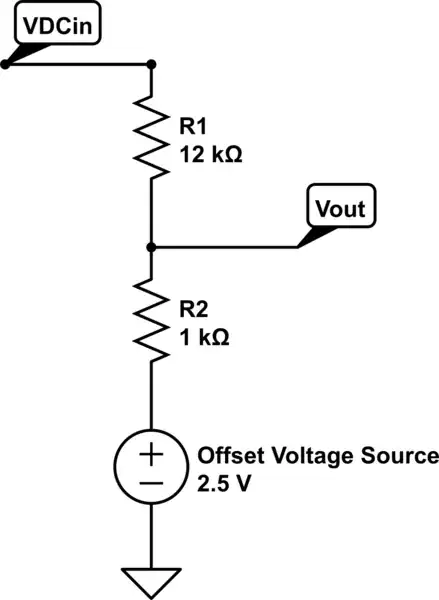
is a resistive level shifter and divider with an output voltage range 2.5V (approximately, see below) to 0V for an input voltage range 0V to -30V respectively. You can solve this circuit using the superposition theorem, for instance. Simply put, it divides the potential between R1 and R2 by 13.
When Vin is -30V, Vout is 0V: the voltage difference between R1+R2 is then 32.5V, which if you divide it by thirteen (R1//R2 = 1 over 12+1) yields 2.5V. That voltage is measured over R2 and makes Vout equal to zero volt. However if Vin is 0V, Vout is slightly under 2.5V: 2.5V - (2.5V / 13) ~= 2.5V - 192mV or 2.31V actually.
If you need a voltage swing up to 5V you need to replace the 2.5V reference with a 5V reference.
When it comes to analogue-to-digital conversion, note that you don't necessarily need to shift voltage levels, for at least two reasons:
Many ADCs have differential inputs, which convert a differential voltage between two inputs, plus and minus Vref. This of course makes sense when measuring negative and positive voltages. It also implies a negative supply voltage to your ADC.
Depending on how you power your ADC, you may very well use the negative line of your voltage input as the ground line for your ADC (or micro-controller) and its power supply. It is possible if the power supply of the A-D converter can float, i.e. if the voltage to be measured has no galvanic connection with the power supply of your ADC.
The latter greatly simplifies the circuitry and keeps the number of input components to a minimum. It also avoids level shifting by performing a relative conversion: just divide the input signal by 6 to have a 0-5V voltage range for your ADC.
You will find relevant responses to a similar question, as pointed to by SunnyBoyNY.