26

Let's assume two options for driving a standard LED at its rated current.

  1. PWM set to 50% duty cycle at 10 kHz
  2. PWM set to 50% duty cycle at 50 kHz

Technically both LEDs would produce the same amount of light and the 'blinking' won't be visible to the human eye or a camera (except maybe for a high speed camera...)

Null
  • 7,448
  • 17
  • 36
  • 48
Gilad
  • 2,087
  • 1
  • 21
  • 25
  • Good question +1 ,I was going to ask something similiar .I would be worried at really low freq like rectified 50Hz due to thermal cycling of the small junction .We will await the answers . – Autistic Dec 21 '15 at 21:45
  • 3
    BTW, some of us humans have eyes that actually *are* sensitive to the PWM blinking. And so some monitor & TV vendors are building flicker-free panels without PWM for dimming. – Basil Bourque Dec 22 '15 at 05:18
  • By "at its rated current" do you mean the current that flows during the "on" portion of the duty cycle, or do you mean the *average* current over the entire cycle? If the latter, clearly there's *some* frequency where the LED can be better said to be pulsing on and off such that the LED is effectively being overdriven during that on time, the question is what the mechanism of damage is and how slow that would have to be. – Chris Stratton Dec 22 '15 at 05:25
  • This might be irrelevant, but that last sentence ("Technically both LEDs would produce the same amount of light...") isn't entirely true; the LED with the higher frequency will produce *less* light than the one with the lower frequency. I learned this here on Electronics Stack Exchange :) http://electronics.stackexchange.com/a/86942/30973 – ayane_m Dec 22 '15 at 06:14

4 Answers4

12

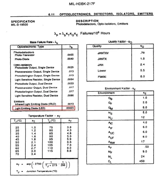
Let me open my trusty MIL-HDBK-217F and see what it says about LEDs and their longevity: -

enter image description here

The main factor affecting the failure rate per million hours is temperature.

Of interest, if I read the next section about laser diodes they do take into account duty cycle pulsing but their conclusion (on page 6-21) is that at 50:50 duty cycle the failure rate for laser diodes is about 25% of that when continually driven.

They also conclude (on page 6-22) that if you operate a laser diode at a light output power of 50% of its rating it will last ten times longer than operating it at 95% of it's rated output power.

Andy aka
  • 434,556
  • 28
  • 351
  • 777
  • This is fascinating, but I have to wonder how these base failure rates were derived. Why should "phototransistor", "photodiode", and "IRLED" fail far more often than "LED" (and none of them specified as to type or application)? What's the confidence interval on any of these values? Why is the temperature factor the same for all devices? This is not to disparage your answer at all--the source clearly says what it says. But I can't help thinking that these calculations--as worst-case values ca. 1991 under unspecified conditions--may only really be meaningful to the US military. – Oleksandr R. Dec 22 '15 at 01:08
  • @OleksandrR. have you since writing this comment done any research on the validity of the mil standard? – Andy aka Dec 22 '15 at 08:06
  • Unfortunately not. I don't know where to start, because nothing is mentioned in the document that would allow one to assess this. Actually, most of it looks completely sensible--but for these very similar devices with such small baseline failure rates, it seems likely that there is some unacknowledged application effect that skews the quoted values. If IRLEDs are high-luminance ones used in IR illuminators, for example. And opto-isolators could easily be failing due to current or voltage stress rather than the LEDs burning out--thus why the phototransistor output ones fail more often. – Oleksandr R. Dec 22 '15 at 10:03
  • 1
    Excuse me. I just saw there is a references section at the end. The LEDs are described in RADC-TR-88-97, where it is noted that just 22 LEDs failed over 4827 million hours of operation, and zero (!) IRLEDs failed over 39 million hours. With such small (or nonexistent) sample sizes, the reason for the odd values is clear. RADC-TR-88-97 also goes into detail about the statistical methods and results. Overall it seems to be a far more meaningful document than MIL-HDBK-217F. – Oleksandr R. Dec 22 '15 at 10:16
  • @OleksandrR. maybe consider making this an answer? – Andy aka Dec 22 '15 at 10:33
6

LEDs are just diodes which don't "wear out" with frequency. The maximum current and average current do affect how the LED wears out, but frequency doesn't have any affect that I've ever heard about.

Also, your frequencies are low. 50 kHz and 50% duty cycle means 10 µs on and 10 µs off. That's a "long" time for a LED.

Olin Lathrop
  • 310,974
  • 36
  • 428
  • 915
  • 1
    It might be a long time for some effects, but for thermal degradation (which apparently dominates) it's very short. – Chris H Dec 22 '15 at 10:24
3

Personal experience:

I've driven a standard UV LED rated for 3.4V, 20mA with about 1A for 5ns at a rate of 87kHz (duty cycle: 1:2300) but didn't observe any "wear" in terms of brightness or pulse shape within 10^11 pulses.

sweber
  • 8,580
  • 1
  • 15
  • 35
  • 1
    Is that about 8,000 days? Oops sorry that's 133 days (less impressive LOL)! – Andy aka Dec 21 '15 at 23:18
  • OT, but how much more luminous flux does it produce under these extremely overdriven conditions? I gather the efficiency falls off fairly rapidly with increasing current (because of the increased rate of carrier recombination at higher die temperatures), but I'm not sure of the actual behavior for brief pulses like this. – Oleksandr R. Dec 22 '15 at 01:15
  • How did you measure the actual current? Seems like it would be tricky to avoid inductive effects, both in the driver and in the current measuring setup itself. – Chris Stratton Dec 22 '15 at 05:30
  • @OleksandrR. : There was a saturation effect, but it was almost neglible. Also because the entire setup had enough other reasons for such effects, I'd say there was no loss in efficiency. However, I didn't care about it too much, it was just important that the amount of light could be steered somehow, and the 1A was an extreme value. – sweber Dec 22 '15 at 09:47
  • @ChrisStratton: Well, I indeed used a very small resistor in series and one of these nice differential 3.5GHz probes from Agilent. Of course, the resistor reduces the current, but interpolation due to the amount of light and estimations from the measured data lead to the conclusion that the current must be about 1A. Sure, this was tough and everything put precise. – sweber Dec 22 '15 at 09:57
  • Have you written any more about this anywhere -- I'm thinking about driving a rather larger UV LED in a similar pulsed mode and there's very little literature (e.g. the data sheet says that the maximum pulsed current is the same as the maximum continuous, but that's the only mention of pulsing). – Chris H Dec 22 '15 at 10:27
2

No discernible impact. The LED itself would only be sensitive to the total lifetime, but reliability is measured in 10's of years.

Thermal failures due to packaging or wire bond failures are more likely, but the probability of failure is still very low. Most likely failure for a self-made system is the solder joints, or wires between the Led and PCB, or PCB and power source.

Thermal failures are caused by different rates of thermal expansion, and the resulting overstress this causes on the structure. Small stresses or stress cycles have negligible effect. Consider that the LED's plastic was probably molded and cured at +175 C -- it is always under stress.

The LED's thermal time constant is probably in the 10-100's of ms range. Cycling faster than that leads to very small temperature excursions which don't cause problems, and cycling slower than that limits the total number of cycles to a very small number.
jp314
  • 18,395
  • 17
  • 46