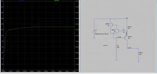
simulate this circuit – Schematic created using CircuitLab
Switch your meter to mA range and connect in series with the battery. I recommend that you add a series resistor to limit the current to protect the battery and meter. 33 Ω will limit the current to about 1/4 A with the pot turned to zero and the LED failed short-circuit.
Be careful with your potentiometer. A standard carbon-film pot might be rated at 0.25 W but that's the rating for the whole track. In the case of your 1 kΩ pot max current would be
$$R = \frac{0.25 W}{1000 Ω} = 0.25 mA$$
You can see from this that a 0.25 W potentiometer might not last too long.
Be careful with your multimeter. As others have pointed out, when measuring resistance your meter applies a small current from the internal battery to the resistor being tested. The voltmeter is usually on a sensitive range because the maximum voltage will be limited to a volt or so. If you were to connect the meter, on resistance range, to a resistor with more than a few volts across it you might damage the meter.
simulate this circuit
Note that the voltmeter has a very high internal resistance and 'all' of the current will go to Rtest. A little goes to the meter but in the case of a digital meter the input impedance is usually about 10 MΩ so it's tiny.
