4

I understand that having an capacitive load at the output of an op-amp can potentially make the circuit unstable. However, how can I go about calculating this?

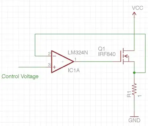
For instance, I'm trying to design a constant current sink (upto 1A at least) using the parts I have lying around: LM324, IRF840 MOSFET etc. Here's the schematic:

enter image description here

The supply for the LM324 is +9V.

The IRF840 has an input capacitance of about 1225pF, which I assume is quite tough for an opamp to drive. My question is: how can I compute that I need a resistor at the output of the opamp to compensate for the capacitive load?

LM324 datasheet

IRF840 datasheet

Saad
  • 5,319
  • 12
  • 60
  • 93
  • Using 1016 pixels horizontally to show such a simple circuit is rediculous and annoying since it's guaranteed to be larger than a lot of people's windows. This circuit would hav been easily understandable with half that or less. Annoying those you seek a favor from is not a smart idea. – Olin Lathrop Oct 09 '11 at 20:00
  • 2
    @OlinLathrop: The images are automatically resized. – endolith Oct 09 '11 at 21:47
  • @endolith: No, they are not. That is dependent on the browser, settings, etc. None of this however changes the fact that 1016 pixels accross for this image is rediculous. – Olin Lathrop Oct 09 '11 at 22:10
  • 7
    @OlinLathrop, it is supposed to rescale it. Lets celebrate whenever we have a user that actually takes the time to upload a schematic. Too many ask questions without. If your browser is not cutting it, there are others also! – Kortuk Oct 10 '11 at 01:26

2 Answers2

6

It's hard to compute this since you don't know for sure where the poles and zeros of the LM324 are.

I would add the components to provide a little immediate negative feedback around the opamp. Sometimes this is called "compensation" feedback. It basically slows down the opamp so that it can't get ahead of the system and thereby oscillate. To add this compensation, put a cap immediately between the opamp output and its inverting input, then add a resistor in series between the FET source and the inverting input. If it turns out the LM324 is slow enough by itself, then you can no-load the capacitor. With a low enough resistor, like 1 kΩ, it won't matter if it stays in series with the inverting input. Having the pads allows you to try different values of capacitors to see what is stable and when the response becomes too slow.

Note that above addresses possible instability regardless of the capacitive load on the opamp output. With capacitive compensation, the opamp should be able to tolerate more capacitive load. You can also add some resistance in series with the gate and then play around with different values of this resistance and the compensation capacitance to get the best tradeoff of stability and responsiveness.
Olin Lathrop
  • 310,974
  • 36
  • 428
  • 915
  • Thanks. Is this is generally how it's done - essentially try different values and see what works best? Are there opamps that tell you where the poles/zeros are in their datasheet? OR, is it a good practice to include the external components for stability anyway? – Saad Oct 09 '11 at 20:03
  • Opamps are usually specified at the minimum closed loop gain that they are stable at without any additional compensation. However, many circuits aren't that simple and have other considerations like yours, so use the specs as a guide, experiment, and derate. – Olin Lathrop Oct 09 '11 at 22:08
2

An old rule, that often works, is just put a 100 ohm resistor in series with the load.

russ_hensel
  • 2,904
  • 16
  • 12