1

I am trying to build an electret microphone amplifier circuit run from a 9V battery. The mic doesn't have a part number on it, so I have been making assumptions based on similar datasheets. Most have impedances measured at 2.2 kΩ, but I have measured mine as 1.2 kΩ. I'm assuming it will draw the same max current, 0.5 mA, and chose a resistor value of 15 kΩ.

With 0.5 mA running through it, theoretically there should be a 7.5 V drop across the resistor, giving a Vmic of 1.5 V and powering it.

schematic

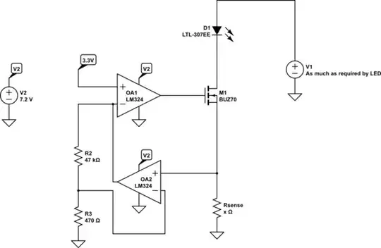
simulate this circuit – Schematic created using CircuitLab

However, when I built this up, I was getting 7.5 V across the microphone, and 1.5 V across the resistor, which I cannot figure out. I'm guessing it's not a voltage divider, and the mic is acting more like a cap. Is it not an electret microphone, or am I missing something?

ocrdu
  • 8,705
  • 21
  • 30
  • 42
pbandjazz
  • 337
  • 1
  • 4
  • 11
  • You may well have killed it. Next time use a lower voltage so the applied potential is less variable. And couple your audio out through a capacitor. – Chris Stratton Dec 14 '15 at 20:20
  • see, for instance, http://www.wildlife-sound.org/equipment/newcomersguide/pip.html figure 3. – Ecnerwal Dec 14 '15 at 20:25
  • I'm thinking it must be blown, since that's the only reason I can think the voltage would be like that. Seems odd though, since most datasheets claim the source voltage can go as high as 10Vdc. – pbandjazz Dec 14 '15 at 21:01
  • Proof of pudding, etc. - please stick in a coupling cap, and then see if you get sound out or not... I suppose the other dumb question would be did you find and follow the often a bit subtle polarity markings on the capsule...? http://electronics.stackexchange.com/questions/145718/do-electret-microphones-have-polarity - but you have no data sheet... – Ecnerwal Dec 14 '15 at 23:19

2 Answers2

2

If you look here you will see that the electret microphone secretly contains a FET! It must, because without it, it is almost impossible to use such a microphone as it is a very small capacitor.

The circuit that you have should be OK but you can try lowering that 15 kΩ resistor to 5.6 kΩ. Don't worry too much about the DC level.

Do use a capacitor (1 μF) to connect to your audio input (unless that already has a coupling capacitor).

Due to the FET, measuring the DC resistance of the electret microphone is meaningless. In my experience they are also quite hard to break, so my guess is that yours will still work.

ocrdu
  • 8,705
  • 21
  • 30
  • 42
Bimpelrekkie
  • 80,139
  • 2
  • 93
  • 183
0

Two-wire electrets are current sinks and the specified current is a maximum value with considerable variation.

0.1 mA is quite low for an electret microphone anyway, but you'll find currents like that for speech-quality microphones (typically with something like a 100 Hz­–10 kHz frequency response) intended for battery-driven devices.

When in doubt: if it works, it works. You probably can safely increase the resistor value (and thus the gain) to get more typical working voltages across the mic.

Measuring impedance is mostly meaningless: since a 2-wire electret is a current source, the impedance of the signal will be whatever your pullup resistor is. If you have measured 1.2 kΩ, that would make your measuring voltage 0.12 V assuming the operating current of 0.1 mA, but at 0.12 V the FET is pretty certainly not at its normal operating point where the current is mostly independent of voltage.

ocrdu
  • 8,705
  • 21
  • 30
  • 42
user107063
  • 2,507
  • 1
  • 13