1

I've seen multiple different explanations on boost converter circuits, these two specifically explaining in very intimate detail how they work, and on how to calculate certain values:

How to design a boost converter? And how to specify the inductor and capacitor values?

Understanding Boost Converter

the basic layout of a boost converter looks like this:

schematic

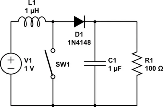
simulate this circuit – Schematic created using CircuitLab

In this example, the 1 volt input would be increased to a higher voltage across the resistor, which would be the load in this case.

Problem:

I need to switch a 5 volt current on the high side with an NPN switch (for many reasons this is the only switch layout available, no other layout will work as desired), so I need 7 volts to the gate to switch it, however only 5 volts are available. For this I need a boost converter that will convert 5 volts to 7 volts to be able to switch the switch

But, I'm not sure how to calculate any of the values. For example, the solutions in the links I provided use the switching time of the switch, how can I find that? What size inductor and capacitor would I need?

Also as an aside, the thing labelled "L" on the diagram, the inductor, what is it's purpose?

Skyler
  • 139
  • 1
  • 9
  • 3
    Before you attempt to design a switching power supply, you need to understand what an inductor fundamentally does. – Funkyguy Dec 11 '15 at 16:25
  • I would like you to clarify two things: 1) Is it correct that you have _another_ circuit that is using a transistor for switching, and that you need _this_ circuit to provide the base drive for the other? 2) Are you sure that it is not possible to use an N-channel MOSFET instead of an NPN transistor? The MOSFET would make the drive easier in this case because you don't need as much current, just voltage, which you can create with a simpler capacitor based step-up. – pipe Dec 11 '15 at 16:30
  • @pipe I'm sorry, I thought n channel mofsets were npn switches. It is in fact an n-channel mofset that I'm referring to here. NTE490 specifically. – Skyler Dec 11 '15 at 16:35
  • 2
    In that case you don't need anything fancy. If you already have a microcontroller you can take a look at this answer: http://electronics.stackexchange.com/a/147975/91862. Otherwise there's the very cheap ICL7660 and clones available. – pipe Dec 11 '15 at 16:41
  • @pipe that answer's circuit won't work. – Andy aka Dec 11 '15 at 18:27
  • You're absolutely right, @Andyaka. That taught me to actually check answers from this site before forwarding them. :) With the modification you mentioned in the answer it will work though, assuming that he has a microcontroller with a pin to spare. – pipe Dec 11 '15 at 19:28
  • Skler - The odds are high that your comment " ... this is the only switch layout available, no other layout will work as desired ..." is not true and that you may be settling for 3d best by not telling people what you are trying to actually do - and perhaps why you think that you know the one valid soution. MANY people ask questions which assume a large range of erroneous things and often waste much of their own and other people's time arriving at the best answer - or never manage. Why not tell people what you wish to achieve rather than what the best way is to achieve an unknown aim? – Russell McMahon Dec 12 '15 at 04:48
  • @RussellMcMahon What I need to use for the circuit I'm making was determined in another question, this is simply the follow up. – Skyler Dec 16 '15 at 16:02
  • @Skyler The information in your head may have been chanelled to you in a Seance, sen in a dream or written in clouds in the sky BUT unless all readers who seek to assst you here were in the same seance or dream (now, there's a trick) or saw the same clouds they remain unaware of what is in your mind. Expecting or presuming that others will search your available public record to try to work out the background to a new question is liable to prove presumptuous. | Worse, looking through you prior SE questions, it's not obvious that any are the one yoiu mention above. IF the prior answer is not ... – Russell McMahon Dec 17 '15 at 01:42
  • @Skyler .... on SE then you indeed are being presumptuous. Why not instead simply cite the prior question if it is online, and/or explain what you are doing? | There is no certainty that what you say is correct and reasonable likelihood that it is incorrect. If you wish to solve a problem and try to do so by compartmentalising each stage so that nobody else has a complete view of what you want then, odds are, if you need to ask the question you will probably get a non optimum answer this way. || Your choices now are to get all indignant at being given advice and react in 1 or more std .... – Russell McMahon Dec 17 '15 at 01:49
  • .... ways **OR** take another look at your overall approach and see if you can improve it to the benefit of yourself and others. There is a lot of extremely good "resource"" on this site. Using it as well as possible is a very good idea. – Russell McMahon Dec 17 '15 at 01:50

3 Answers3

5

Also as an aside, the thing labelled "L" on the diagram, the inductor, what is it's purpose?

If you have an elastic band stretched across an opening and you pull it down in the middle (to ground) then release it, said elastic band responds by rapidly rising and if you have your hand in the way then you can get a slightly painful little recoil slap. Here's a nice picture to consider: -

enter image description here

You can fire the little object attached to the rubber band quite a distance.

Now that analogy isn't precisely what happens with the inductor but it's near enough to make use of.

So, instead of allowing the elastic band to freely recoil (and waste all the energy you have put into it), imagine you mechanically harvested that recoil to push a little mass/object a little bit higher each time you released the elastic band.

You'd need the mechanical equivalent of a diode so that when the elastic band was pulled down you didn't return the object/mass to ground. That wouldn't be too hard to build but you don't need to build it - you just need to understand the analogy.

So, to get 7V from 5V you need to turn on the transistor for long enough to build up a certain current - that current defines the energy stored in the coil and when that energy is released via the diode and into the capacitor and load, it's enough energy to keep it at 7V and the cap is big enough so that the 7V doesn't droop too much when the inductor is being pulled to ground.

However, the difficulty arises when you try and control the output voltage to a precise value - it is highly load dependent and highly input voltage dependent and so normally what happens is that an op-amp control loop defines the duty cycle of the inductor to prevent too big an output voltage being generated.

Andy aka
  • 434,556
  • 28
  • 351
  • 777
  • Thank you for this info, I'm new to electrical engineering and this may greatly help me in the near future. – Skyler Dec 11 '15 at 16:33
  • I think that example is more analogous to a capacitor rather than an inductor. A more appropriate mechanical equivelant of inductance is inertia, as for example the [hydraulic ram pump](https://en.wikipedia.org/wiki/Hydraulic_ram) is the water version of a boost converter, and the inertia of the water performs the same function of the inductor in the electrical circuit. – whatsisname Dec 11 '15 at 18:15
  • @whatsisname - it's an analogy and a capacitor can certainly be modelled as a flyweel possessing inertia. They are interchangeable analogies. – Andy aka Dec 11 '15 at 18:18
  • Electricity doesn't behave quite like anything else, so analogies always break down at some point. The key is understanding that energy is being stored in the magnetic field, and later that same energy is released in a slightly different form. – MarkU Dec 11 '15 at 21:45
  • I've used a water under pressure flowing through a rubber tube analog. The tube balloons under pressure, resists flow, stores and releases energy, ... . The model isn't perfect (of course). – Russell McMahon Mar 05 '20 at 01:39
3

The simplest solution would be to use a small, integrated boost IC. For example here is one from TI, but there are lots of other choices from other vendors as well (The component value choices are clearly explained in the datasheet):

TPS61046

However, you mention you need 2V above your 5V rail to switch your FET. Are you sure that you will be able to turn the FET fully on with 2V VGS? Most FETs have a threshold voltage in the 2V region meaning they are just starting to conduct there. You may want to switch the gate with 5V Vgs or a 10V boosted supply.

If you don't need the FET to be on continuously, and you have a defined minimum off time you may be able to use a bootstrap circuit to generate the gate drive voltage. Without knowing more about what you are doing it's impossible to say if a that would work or not. You might start another thread with more details if you don't know how to make a bootstrap work.

Finally, the purpose of the inductor is energy storage. When the switch is on the current in the inductor ramps up according to V=L*di/dt. The output voltage is held up by the output cap and the diode isolates the output from the switch. The energy stored is 1/2*L*I^2. Then when the switch turns off the inductor ramps down, though at this point the voltage across the inductor is in the opposite direction and equal to Vout-Vin. So the inductor provides energy to the output during the off time, allowing the output voltage to rise above the input voltage.

John D
  • 22,677
  • 1
  • 39
  • 56
  • Thank you very much! I think this will lead me in just the right direction. :) – Skyler Dec 11 '15 at 16:32
  • So John, this ICU is actually only 0.8 x 1.2 mm, which ironically is a bit too compact. Way too small to work with! If you know of any others off of the top your head that are large enough to at least be soldered to without advanced machinery. If so, thank you, and if not, thank you very much again for your help. – Skyler Dec 11 '15 at 18:07
  • 1
    Here's a part in a SOT-23-5 package, which I find pretty easy to work with manually. http://www.ti.com/lit/ds/symlink/lmr64010.pdf – John D Dec 11 '15 at 18:18
0

May be this is not a direct answer but it gives a simple explanation, using old time experience in boost and buck converters using transformers.

BOOST

enter image description here

BUCK

enter image description here

GR Tech
  • 2,208
  • 2
  • 15
  • 17
  • This is just regular old transformer usage, boost and buck converters exploit the transient behavior of inductors rather than their steady states. – whatsisname Dec 11 '15 at 18:21
  • Or a `variable autotransformer` effectively can do both. But only for AC input & AC output; OP is asking about DC to DC converter. – MarkU Dec 11 '15 at 21:49