1

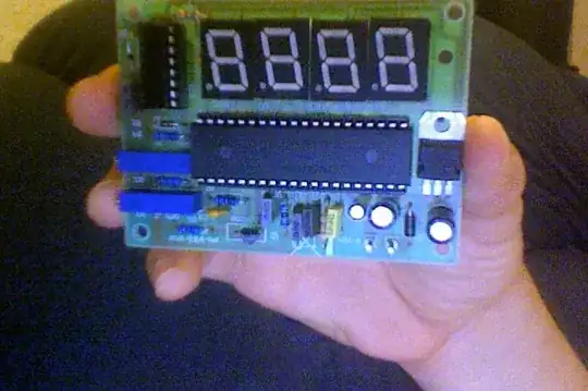
I did finish a circuit, but it is not working. It is a LED thermometer. I assume that is not working, because It doesn't show nothing in the LED display.

To debug i followed the steps:

  • I turned on my power suppy in 9V (it is recommended something between 7V-18V).

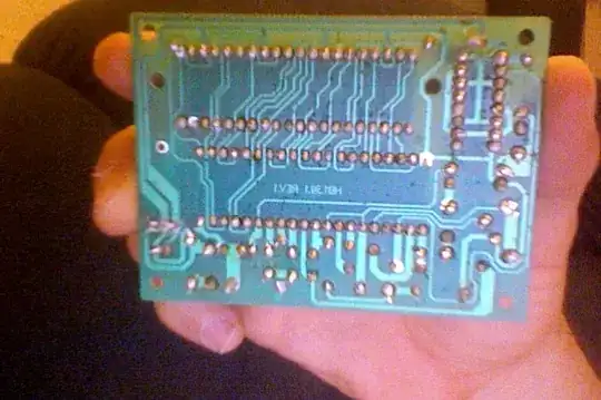
  • With my multimeter i touched some components, looking for short circuit. So capacitors, resistors, diodes and an ICS switch are, at least receiving energy.

What else can I do to find out why it is not working? Or at least to identify which component is the problematic one? As I wrote before, I did test all components and they are receiving and transfering energy, but how can I debug the IC switch or another specific component?

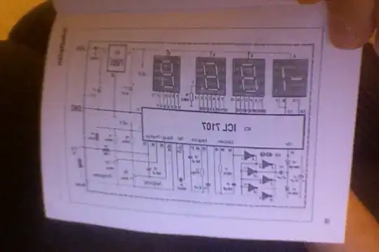
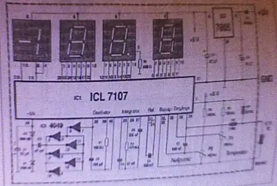
Photos from circuit and schematics

mounted circuit solded surface schematics

Fizz
  • 14,355
  • 2
  • 43
  • 97
VP.
  • 238
  • 1
  • 2
  • 16

2 Answers2

1

ICL7107 datasheet here

Bigger and well focused photos will help.
Having left and right not reversed will help.

Some solder joints look "blobby". They should be shiny (if lead based solder isused) and flow smoothly onto pads.

Set meter to continuuty or "beeper" mode if available.
Otherwise use lowest ohms range.
Check for shorts between all adjacent (side by side ) pins with meter.
Any that are joined - check if they are meant to be.

IC's in correct orientation?

All diodes and capacitors with correct polarity?

What is small TO92 pg device at bottom of picture slightly off centre to left?

enter image description here

Russell McMahon
  • 147,325
  • 18
  • 210
  • 386
  • which picture you mean? schematics or the picture from the device? You mean the blue one? – VP. Oct 06 '11 at 12:10
  • @VP01 - It is likely that you have shorted between two pins with solder, or not soldered a joint properly, or inserted a component incorrectly (eg reversed) or used a wrong component in a given location OR a number of each of these. If you want people at up to 19,000 kilometres away from you to help well THEN the best possible photos of everything relevant would help immensely. // PCB: both sides - Use lots of light, fill the picture space available, focus properly, possibly send two photos per side. – Russell McMahon Oct 06 '11 at 12:22
  • **Photos:**eg [Look here](http://public.fotki.com/RussellMc/atw/bogo/sn2pcb/sn2pcbdsc00684r1.html) click icon 3rd from right at top of photo. Click to expand. You have a chance of spotting bad solder joints or bridges with a photo at this resolution. – Russell McMahon Oct 06 '11 at 12:24
  • yes i will provide better pictures. Question: if there were any component in wrong direction, diodes and capacitors, for example, when I check the next component, should it be energized? For example. If one diode is inverted, the next component, a capacitor for example, won't store any energy right? – VP. Oct 06 '11 at 16:31
  • @VP01 - you would need to look at the circuit diagram. A reverse diode may energise at a different time. A reversed zener diode is "different", a reversed capacitor may gib=ve low capacitance (aluminum elecrolytic) or explode (Tantalum) or be OK (non polar). – Russell McMahon Oct 06 '11 at 17:42
0

How exactly is it not working?

For instance is the display lighting up? (if not check power to appropriate pins)
If it is, what does it read? Does it change at all? What are the voltages read at various pins?

I would check the oscillator (do you have an oscilloscope?) and what looks like a negative supply generator driven by it. I think you should read a negative voltage (probably around -3 volts) on the bottom left pin in Russell's picture. Check the (10uF?) polarised cap on the far left is the right way round (positive to ground) I am also curious about the TO-92 package - is that the temp sensor? What is the part number and how is it connected?

Oli Glaser
  • 54,990
  • 3
  • 76
  • 147
  • it doesn't show nothing in the LED display – VP. Oct 06 '11 at 12:05
  • that is a temp sensor. one leg is connected to one resistor and another leg connected to the ICL7107 – VP. Oct 06 '11 at 20:16
  • 1
    What is the part number for the temp sensor? The fact it doesn't show anything at all on the display sounds like it is something like no power present to the ICL7107 or an open circuit on the common side of the display between it and the 7805. Make sure the ICL7107 is the right way round (and the display) and measure voltages at it's power pins. Check continuity between power and ground lines to make sure there is no short. Edit your answer with as much information as possible regarding testing e.g. voltages at different points, circuit activity, etc. – Oli Glaser Oct 06 '11 at 20:42