3

I am working on a water monitoring system that needs to read ph in ADC of microcontroller(0-3.3V)

I understand how ph sensors work...just -.41V(0ph) to +.41V(14ph)...

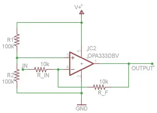
I have an understanding of designing the circuit to amplify and scale this so that the microcontroller can read it.

  1. Is there a significant advantage using a 5V microcontroller to get a larger voltage range? The micro I want to use is 3.3V with max 3.6V on the ADC, 12 bits. If I chose a 5V micro or off chip ADC, would I get more accurate results? Obviously the amp circuit will be a factor here, but consider it the same circuit with different gains etc...

  2. How can I supply negative voltage to the op amps? This will be in an embedded system and will have access to 120VAC input. Are there negative voltage regulators that supply enough power for an opamp and that can get me negative voltage w.r.t ground?

Kortuk
  • 13,362
  • 8
  • 60
  • 85
user623879
  • 217
  • 1
  • 3
  • 10
  • 1
    'Max 3.6V' is the maximum the input can sustain without damage. Anything over 3.3 (minus one step) will saturate the ADC. Also, what's your PH probe's resolution? A 12 bit ADC will give you 2^12 = 4096 separate readings, or a 0.0034 PH resolution. I doubt that your probe is that accurate. – Kevin Vermeer Oct 05 '11 at 14:46
  • @user623879, Currently your questions have very similar titles. So that others can find the same helpful advice you received could you possibly reword your titles more for what you are specifically needing? I have taken a shot(albeit a poor one) at your current title, I would appreciate it if you or the community could take a shot at getting this title and other approved. – Kortuk Oct 23 '11 at 05:31
  • If you are into reliable soil moisture measurement, then take a look **[here](http://electronics.stackexchange.com/questions/9455/soil-moisture-measurement/9494#9494)**. – avra Oct 05 '11 at 10:44

2 Answers2

4

The accuracy of the ADC is determined by the number of bits. A higher voltage range for the ADC would stretch the bits out reducing the resolution, or rather increasing the step voltage.

You don't need a negative voltage for the op-amps if you offset the input by Vcc/2 with a simple voltage divider. This could be in the form of a false ground reference to the input of the op-amp, as shown in this schematic:

enter image description here

On a 3.3V system that would off-set the input voltage by 1.65V making it from 2.06V for 0PH to 1.24V for 14PH.

Increasing R_F by a factor of 2 would increase the gain to 2:1 making it a +/- -.82V swing - 2.47V to 0.83V thus increasing your precision.

A further increase of R_F could increase your precision more, until you hit the top/bottom end of the output headroom. A "Rail-to-Rail" op-amp would give you more headroom than a normal one.

Majenko
  • 55,955
  • 9
  • 105
  • 187
  • Does applying ground to the V- terminal have any implications? Does applying 2Vcc to V+ have any implications? Let's assume the opamp requires +-10V, is it ok to supply 20V to the V+ and 10 to ground and 0 to V-? – user623879 Oct 05 '11 at 08:57
  • Agreed on ADC accuracy, but by scaling down from 0-5V range to 0-3.3V range, do I lose any precision or would this not really matter at all? – user623879 Oct 05 '11 at 08:59
  • If you scale the input signal to match the ADC range the precision will stay the same. If you don't, the precision will be reduced. As for the op-amp I would apply half of Vcc to the non-inverting input and the signal onto the inverting input, with feedback to increase the gain. The resulting signal will be upside down so you will have to compensate in software. That is probably the simplest way. – Majenko Oct 05 '11 at 09:04
  • 1
    Not sure that it is a good idea to put the signal of the ph probe onto the opamp negative terminal. The ph probe is not a good current source and so need to minimize current drawn otherwise voltage will drop too much for it to be useful. – user623879 Oct 05 '11 at 09:20
  • @user623879 - I think you're misunderstanding the circuit. I've drawn what I understand to be Majenko's proposal above. The PH probe doesn't need to be a good current source - is 10k or 100k input impedance acceptable? If not, there are other op-amp configurations which offer higher input impedances. – Kevin Vermeer Oct 05 '11 at 14:45
  • @KevinVermeer Thanks - that's exactly what I was meaning. I was on my phone earlier and unable to draw schematics. – Majenko Oct 05 '11 at 14:53
  • Thanks for drawing schematic. I understand what you mean, but as mikeselectricstuff said, ph probe needs super high impedence. Also, what tool do you use for drawing the schematic? – user623879 Oct 05 '11 at 18:57
  • That looks like Eagle to me. Personally, as a Linux user, I use gEDA gschem. – Majenko Oct 05 '11 at 19:06
2

From what I recall, Ph probes need a very high input impedance, so you may not be able to put any kind of resistive divider on the input, and may either need a -ve rail on the opamp/input buffer or a voltage offset on the probe ground.

mikeselectricstuff
  • 10,655
  • 33
  • 34