0

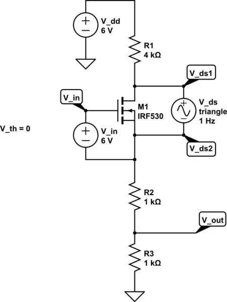
I wanted to simulate the linear region, so I tried this:

schematic

simulate this circuit – Schematic created using CircuitLab

I expected the triangle wave to be curved, but it didn't have those features. Am I doing something wrong or am I expecting the wrong results?

How does one usually simulate the linear region in SPICE?

Or do I have to make a lumped model of an NMOS for it to display the linear region?

EDIT:

schematic

simulate this circuit

I suppose this would be the more appropriate setup. The triangle \$V_{ds}\$ no longer creates a triangular \$V_{ov}\$. Making everything clearer to think about. Still, as in the previous schematic, the question remains, I was expecting curves, instead of straight lines.

EDIT:

Has anybody tied breadboarding the fist circuit and measured it with an oscilloscope? I just realized that it might not actually have significant curves. As the \$V_{in}\$ varied in phase with \$V_{ds}\$, that might compensate for the the expected upside down parabola of a varying \$V_{ds}\$, making it a lot less curved.

kozner
  • 319
  • 1
  • 3
  • 12
  • 2
    If you're connecting a voltage source across the FET, the FET isn't doing anything useful. Normally you would connect your input signal in series with the bias generator V_in (6v) and measure the source and drain voltages. Or perhaps I *really* don't understand what you're trying to do. –  Dec 06 '15 at 16:03
  • Spice uses lumped models (for FETs and for pretty much everything except transmission lines) so that part of your question makes even less sense. – Fizz Dec 06 '15 at 21:19
  • Also, you'll have to clarify [what you mean by linear region](http://electronics.stackexchange.com/a/204711/54580) before someone can answer. – Fizz Dec 06 '15 at 22:19
  • @RespawnedFluff OK, I meant the reverse of a lumped model. A mass collection of different components, meant to simulate a single one. – kozner Dec 07 '15 at 05:45

1 Answers1

1

The SPICE model will work correctly. As drawn, your FET is in the linear region, and if you superimpose a small triangle on the input, you'll get a small triangle at the output because it modulates the RDSON of the device.

jp314
  • 18,395
  • 17
  • 46
  • But would it displace curves instead of straight lines? This would all be much easier if I only an an oscilloscope... – kozner Dec 07 '15 at 05:44
  • In your circuit, the FET has 4k in the drain, and 2k in the source. With 6 V on the gate pin, the VDS will be small (10's of mV), and VD ~= VS = 2 V. This gives the FET VGS=4 V, and an RDSON proportional to 1/(VGS-VT). The 2k & 4k make an approximately constant drain current, and so the VDS will be proportional to the RDSON of the device. – jp314 Dec 07 '15 at 05:53
  • ^Sorry, my meant to type "display" – kozner Dec 07 '15 at 06:06
  • I didn't get all that you were saying, but why is \$R_{dson}\$ proportional to to \$1/(V_{ov})\$, instead of \$V_{ds}\$?? – kozner Dec 07 '15 at 06:11
  • in a FET, with VGS > VT, and VDS 'small', the RDSON is proportional to 1/(VGS-VT). You can derive that from the Shichman-Hodges model – jp314 Dec 08 '15 at 03:41