My concern is that the low level produced by the PNP will be just under \$0.7\mathrm{V}\$ because of the required \$V_{be}\$ for the transistor to be on. For \$5\mathrm{V}\$ CMOS, the low level input voltage is usually at most \$0.8\mathrm{V}\$ (for \$3.3\mathrm{V}\$ CMOS it will be a little lower), which means you are right on the edge. Personally I wouldn't be happy to run that close to the edge.
In fact, now that I have had a go simulating the circuit, I'm not convinced it will work as planned when floating. Q2 won't turn off properly unless you add a pull up resistor - but in order to be strong enough to work, it would cause Q1 to turn on.
There is a way I have done this in the past, but it requires two comparators. This isn't too bad as a dual-comparator package is only 8 pins and would take up about the same as your discreet transistors.
Basically the approach is to turn the input into ternary - you have equal pull-up and pull-down resistors so that when floating the input voltage will be about half the power rail.
You then have a comparator for each output. For the first device the comparator is set up so that it outputs a low only when the voltage is less than one third of the power supply. For the second device you output a low when the voltage is above two-thirds of the power supply.
It will require 5 resistors and 1 dual-comparator. The circuit is as follows:
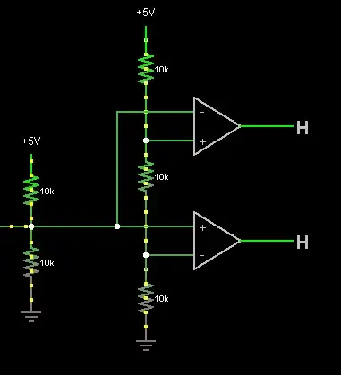
The above can be simulated here. It's simulated for \$5\mathrm{V}\$, but the circuit would be identical for \$3.3\mathrm{V}\$.
Essentially the top comparator will be low only when the input is driven high. The bottom comparator will be low only when the input is driven low. If the input floats, both comparator outputs will be high. This is almost a Ternary to Binary converter circuit, it's not strictly speaking as you need the outputs 01,10,11, whereas ternary would be 00,10(or 01),11, but its essentially the same thing just with one bit inverted (hence the comparator is the other way up).
If the comparators are open-drain, which many are, you will also need a pull-up resistor on each output. This shouldn't cause a problem as you will get a nice strong logic 0.

