5

I am designing an activity where students should band pass a song to find a hidden message at 1000Hz.

Problem

I have considered using a notch filter and tank circuit, but using the formula $$f=\frac{1}{2\pi\sqrt{LC}}$$ I cannot reach the range of 1000Hz with my variable capacitor. Is there a clever way to achieve a circuit to filter 1000Hz and use my variable capacitor for tuning?


At my disposal:

  • A variable capacitor (20-350pF)
  • Various capacitor values ranging from 100pF to 220uF. (I can find more if need be)
  • Inductors ranging from 250uH to 3mH
  • The drive to work on the weekend because I find this project so interesting.
Klik
  • 803
  • 1
  • 9
  • 24

4 Answers4

7

You could try an op-amp capacitance multiplier circuit:

Opamp capacitance multiplier (Courtesy of Wikipedia)

C = C1 * R1 / R2, so adjust R1 / R2 to provide the level of multiplication desired. Note that some op-amps have trouble driving capacitive loads. So if you connect a significant-enough capacitance to the op-amp output, it may oscillate.

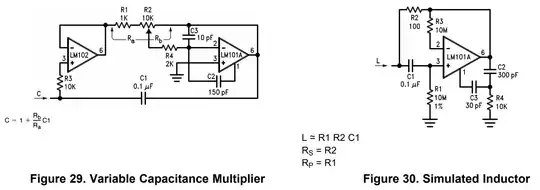
Edit: A variant to try is this one. It uses the LM102 to buffer the input current, mostly eliminating the "resistance factor" from the previous circuit. I have not tested it, but would be skeptical of it's performance with very small capacitances. Also note that since C1 is being driven by the LM101A, this is "capacitive loading" and some op-amps could oscillate in this configuration. Some experimentation would be required. (Courtesy Texas Instruments) TI LM101A Datasheet

rdtsc
  • 15,913
  • 4
  • 30
  • 67
  • 1
    This is an excellent idea and it's exactly why I asked this question. I'm not sure if it will behave appropriately in my band pass circuit, but I will try it out. – Klik Nov 25 '15 at 03:33
  • I have seen this circuit on the LM101A datasheet. May I know with respect to which point 'C' is measured? Ground? – Amalnath Satyan Dec 06 '19 at 04:33
  • 1
    @AmalnathSatyan that is correct. Power the op-amps from a +/-15v supply for best results. Of course this also means that the voltage of the simulated capacitor is limited to near that range. – rdtsc Dec 09 '19 at 01:36
4

Given your variable cap and your need for a fairly wide tuning range, I'm afraid you're out of luck. Consider: from your formula $$f=\frac{1}{2\pi\sqrt{LC}}$$ $$LC=\frac{1}{{(2\pi f)}^2} = 2.5\times 10^{-8}$$ so $$C=\frac{1}{L{(2\pi f)}^2} = \frac{2.5\times 10^{-8}}{L}$$ and for a 3 mH inductor $$C= 8.45\times 10^{-6}$$ If you pad your tuner with 8.5 uF, and assume 0 pF on the tuner, you'll get a nominal frequency of $$f=\frac{1}{2\pi\sqrt{LC}} = 1.0028356 kHz$$ Cranking up tuner to 350 pF will give $$f=\frac{1}{2\pi\sqrt{L(C+\Delta C)}}=1.0028562 \text{kHz}$$ Basically, unless you can get much bigger inductors, your capacitance range is just too small to be useful.

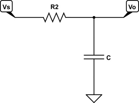
A capacitance multiplier may sound like a good idea, but as presented it is not applicable. The circuit shown does not produce a pure capacitance. Instead, it is the equivalent of

schematic

simulate this circuit – Schematic created using CircuitLab where C is the multiplied value. You will find that this is not exactly a useful circuit for what you want to do.

WhatRoughBeast
  • 59,978
  • 2
  • 37
  • 97
2

Simply stick some fixed capacitors in parallel with the variable capacitor until you get to the capacitance you need -- your tuning range will be limited, but the resistor analog of this is a common way of implementing a "fine trim" type of control that operates on some sort of control voltage.

ThreePhaseEel
  • 8,858
  • 4
  • 26
  • 41
  • 2
    I thought about that as well, but then it limits my range significantly. The goal of my circuit is to give the student a sizeable amount of range to experiment over. If I use this method, I'm afraid there won't be enough range for the students to "miss" the signal and I'll be essentially handing them the answer. I'd like them to experience the significance of a Q value (if I can manage to get it selective enough). – Klik Nov 25 '15 at 03:33
  • @Klik -- how many sections does your variable capacitor have? – ThreePhaseEel Nov 25 '15 at 04:14
  • @Klik -- also, how about having a switch or set of switches so that the student can switch various fixed caps in and out? – ThreePhaseEel Nov 25 '15 at 23:20
  • I'm not sure what you mean by sections. It is an air variable cap typically used for AM receiver applications. That's not a bad idea to use switches, but then it would increase the cost of parts required to make it work for 200 students. – Klik Nov 25 '15 at 23:37
  • 1
    @Klik -- many large air variable capacitors are actually several capacitors mounted onto the same shaft so that they all tune together -- this was how multiple radio stages were tuned at the same time in ye olden days – ThreePhaseEel Nov 26 '15 at 00:46
0

You could use your variable caps and fixed inductors to make a LC oscillator .Of course the frequency will be far too high but you could use it to clock a switched capacitor bandpass filter which these days would come in a simple 8 pin chip .Switched cap filters do have snags and the old MF4 is featured in www.badbeetles.com . I am assuming that you will pick a more modern chip thats more suited to be a high Q filter.If you dont want to do this you could at a pinch make a active bandpass filter out of high impedence elements like TLo74 MPF102 using your variable caps with some fixed cap in paralell and high value resistors ..In fact the old Hatfield LMS measuring set has a variable cap in it and it runs down to 20Hz using a wien bridge.

Autistic
  • 14,235
  • 2
  • 27
  • 65