I have created a very simple circuit using arduino, in which I have 4 switches used to control the lamp ON/OFF as shown in the below schematic.
simulate this circuit – Schematic created using CircuitLab
Here is the program written in Arduino IDE:
int switch1 = 8;
int switch2 = 9;
int switch3 = 10;
int switch4 = 11;
int outputPin = 12;

void setup()
{
    pinMode(switch1, INPUT);
    pinMode(switch2, INPUT);
    pinMode(switch3, INPUT);
    pinMode(switch4, INPUT);
    pinMode(outputPin, OUTPUT);
}

void loop()
{
    if(digitalRead(switch2) || digitalRead(switch4))
    {
        digitalWrite(outputPin, HIGH);
    }

    if(digitalRead(switch1) && digitalRead(switch2))
    {
        digitalWrite(outputPin, LOW);
    }
}
Basically, my original project has a Motor instead of Lamp, & the four switches shown above are the two pairs of switches in each tank. i.e. I have two tanks and two switches in each tank. 1 switch at the bottom of the tank to measure the water level. If tank is empty then this switch will be open. Another switch at the top of the tank, which will verify that if the tank is full or not and accordingly it will turn on/off the valve which is not shown in the below diagrams, as I think it's not necessary now.
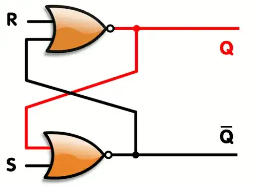
The above circuit works perfectly, but now I want to complete the same circuit using logic gates, instead of arduino. I have tried the circuit shown in below schematic, but I was not successful as I am new to electronics & Logic gates.
I want to use logic gates instead of Arduino to bring down the cost.
Thanks for any help.