8

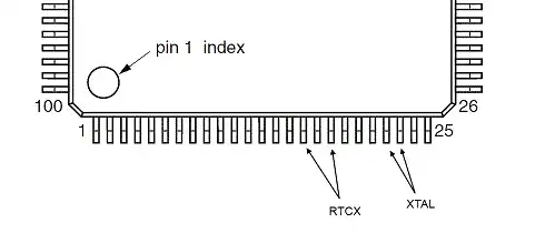
I'm routing a breakout board for NXP's LPC23xx microcontroller. This MCU requires two crystals if one is using the RTC. These two crystals connect to the MCU with only 3 pins in between:

LQFP-100 package with crystal pins indicated

From this question, it is clear that "as close as possible" is the recommended distance, but there are tradeoffs to be made, especially when dealing with two different crystals that must be connected "as close as possible" and with traces that are "as symmetrical as possible".

In my particular design, I'd like to use rather large crystal packages (TC38 for the RTC and SM49 for the 12 MHz) for cost reasons, but even with much tinier packages, layout is not simple.

Therefore, we have several factors to consider when laying out a PCB with these two crystals:

  1. Crystal trace length
  2. Crystal trace symmetry
  3. Capacitor trace length
  4. Capacitor trace symmetry
  5. Common ground connection for capacitors

And, of course, each of these exists for both crystals.

How should I prioritize these factors? Should I sacrifice trace symmetry in order to minimize the length of one of the traces? Should I make the traces as symmetrical as possible, even if that means that the traces will be ~12mm long? Further, which of these crystals should I place closer, assuming I can choose one to be close and one to be further away?

Mark
  • 4,650
  • 10
  • 48
  • 53
  • I don't know the answer to this, but I do know that I tend to prefer symmetry over length. As for which to have closer - I'd be inclined to have the RTC one closer as that is more critical for accuracy (unless you are doing precise timing with the chip). – Majenko Sep 29 '11 at 15:03
  • So RTC is running at 32768 and the other is at 12 MHz? – Kortuk Sep 29 '11 at 15:04
  • @kortuk That's how I'd read it... – Majenko Sep 29 '11 at 15:14
  • 2
    @Kortuk yes, the "main" crystal is 12 MHz, and the RTC crystal is 32.768 KHz. – Mark Sep 29 '11 at 15:17
  • @Mark, I have seen people use crystals in the MHz for their RTC also, they just divide perfectly, thought I would clarify. – Kortuk Sep 29 '11 at 15:20
  • 2
    I'm not an expert at this, but I don't think you need symmetry, because the two pins for a crystal are asymmetric. One pin is output and the other is input. Maybe you rather need symmetry w.r.t. the load capacitors. – starblue Sep 29 '11 at 15:41
  • @starblue: the crystal pins aren't polarized, there's no "crystal +" and "crystal -". If they're asymmetric, there's no way to know which is which... – Mark Sep 29 '11 at 15:52
  • Is the RTC oscillator optimized for power on this chip? I know on the nanowatt PICs and MSP430, the 32768 oscillator is designed to deliver only enough power to barely oscillate, and layout is very important. TI has an appnote about it: http://focus.ti.com/general/docs/lit/getliterature.tsp?literatureNumber=slaa322b&fileType=pdf – markrages Sep 29 '11 at 16:12
  • 1
    @Mark, the crystal pins are symmetric, but the pins on the chip aren't. I also don't understand the requirement for the trace symmetry. – avakar Sep 29 '11 at 16:19
  • @markrages: the NXP datasheet is specific in that the traces should be as short as possible, but that's all the information it gives. There is information on how to choose the capacitors based on the crystal load capacitance, but that's it. – Mark Sep 29 '11 at 16:22

2 Answers2

2

The idea behind simmetry of crystal connections is that they would pick equal amount of EMI and majority of it would be cancelled out. As it was mentioned, in low-power application crystal is driven as weak as possible, so it might be very easy to disrupt it's generation.

32kHz crystal is the most sensitive.

Also, please add to your points that you need exactly 1 connection point from GND to caps. You cannot connect them to ground wire/plate in different places, because then current flowing on the ground wire/plate will generate non-compensated noice on the crystal.

BarsMonster
  • 3,267
  • 4
  • 45
  • 79
  • Both of the designs I've based mine on have separate connections to the ground plane for the caps... so it's certainly possible to make it work, ideal or not. – Mark Sep 29 '11 at 19:30
  • That starts to matter at frequencies in the VHF range but it isn't a big concern at 12 MHz. Excessive inductance in the ground path is always a concern but at 12 MHz you almost have to try to screw it up. – John Miles Sep 30 '11 at 07:13
1

For either of those parts 50 mils (~1.3 mm) of difference in length would be just fine. I would rather see you give up some there rather than have the crystal 12 mm away.

Brian Carlton
  • 13,252
  • 5
  • 43
  • 64
  • 1
    It's important to note that because of the location of the pins, one or the other crystal will have to be significantly farther than the other. Furthermore, the package of the 12 MHz crystal itself is something like 10mm wide. – Mark Sep 29 '11 at 20:04