1

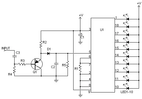
I have used the circuit diagram that is on page 2 of this datasheet and it works pretty much. I am getting the signal off the output of my computer which has been cut and then feed into my circuit and to the Logitech speakers I run my sound through.

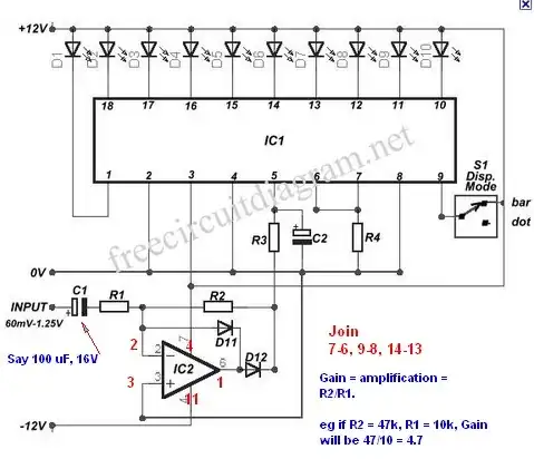
I was wondering how and where would I introduce a part to change the sensitivity of the circuit. To make circuit light up more LED's with a lower signal level and vice-versa?

I'm also not sure that voltage of is the V+ that is I connect to the LEDs (top right of the diagram) is meant to be? I have connected it to 5V which is powering the whole circuit - do I need to place a resistor there to bring the voltage down for the LEDs?

Ashley Hughes
  • 1,225
  • 4
  • 19
  • 25

2 Answers2

2

It just so happens that Dave Jones has posted an interesting video tutorial in which he explains how to use the LM3914 dot/bargraph display driver chip. The difference between your chip and the one used in the video is that LM3915 is logarithmic and the LM3914 is linear. Other than that, they work pretty much the same. I highly recommend this video.

m.Alin
  • 10,638
  • 19
  • 62
  • 89
  • 1
    It is a GREAT video even if you need the logarithmic lm3915 his videos cover a great deal that would work for both, going to rewatch it today to calculate the led brightness – Ashley Hughes Oct 01 '11 at 22:49
1

The data sheet provides information on brightness levels with supply voltage and related matters. Putting effort into trying to find out that information yourself from the data sheet will be rewarded by a much greater familiarity with the IC longer term. (Probably :-) ).

A 5V supply is acceptable.

Reducing the number of LEDs lit can be achieved by turning the volume down or adding a potentiometer at the input. (Pot/variable resistor/volume control).

If the IC is not sensitive enough for you then you can get "more LEDs per volume" with this circuit and similar. IC2 can be an LM324 or LM358. The -12V supply shown is not required. Discuss.

LM324 DATASHEET here

  • LM324 pinouts as shown in red below.

  • R4 from datasheet. (10k?)

  • C2 say 10 uF to 10 uF.

  • R3 probably say 10K. Maybe more.
    R3 + C2 smooth input signal. Delay time = R x C.
    10 uF x 10k = 0.1 seconds.
    Bigger Cap or $ will make it slower to change.

Classic opamp gain is - R2/R1.
D12 pass + music peaks to display IC. D11 stops op amp trying to go -ve.

enter image description here

This may also be worth a try. Ask if interested.

enter image description here

Passerby
  • 72,580
  • 7
  • 90
  • 202
Russell McMahon
  • 147,325
  • 18
  • 210
  • 386
  • The second version of the circuit I should have the parts around. Q1 is a PNP transistor would something like a BC548 work? Then how do I calculate the rest of the values? I would prefer help calculating them instead of just values. As you said it will be better for me – Ashley Hughes Sep 28 '11 at 22:58
  • I purchased a LM324 op-amp today as well, if you could explain the values of the resistors and capacitors would be awesome – Ashley Hughes Sep 29 '11 at 04:54
  • Ok so changing the ratio between R2/R1 will allow me to adjust the input level into the LM3915 the join part on the diagram refers to the spare pins on the op-amp I assume. I will start with a factor of 4.7 and maybe add a pot in series to allow me to adjust R1 as I don't believe I will need a factor greater than 4.7 so a pot after would then lower the factor. – Ashley Hughes Oct 01 '11 at 03:10
  • what diodes are they I have 1N4004 and some smaller ones as well – Ashley Hughes Oct 01 '11 at 05:51
  • 1N400x would work, but better to use a "small signal diode. Your small diodes would probably be small standard silicon diodes so would be OK. Be sure they are not small zeners. The 'classic' small signal diode is the 1N4148 but there are many that would be suitable. IF you have a meter with a diode test feature (usually associated with lowest resistance ohmsrange). Silicon forward voltage drop will show as about 600 on most diode tests whereas zeners have a higher reading - 800+ from memory. – Russell McMahon Oct 01 '11 at 10:26
  • I am using 4148 high speed diodes I have around, now it works with some modifications, I have gone from bread board to a diagram which has confused me as how i fixed it is not how i thought i did if that makes sense https://files.me.com/ashley.hughes/gt766s <- diagram I halfed the input using a voltage divider as I got a constant 4 bars and modified a cap value as there was little to no movement on the display, but I thought I put the divider some where else I needed it as I am not using a dual power supply? – Ashley Hughes Oct 01 '11 at 10:35
  • @Ashley Hughes - IF the opamp is connected as shown then it is wrond and it will not function as an opamp. You have swapped the two opamp inputs. It now has no "negative feedback and will simply behave staangely in that circuit. You have added extra components and is is hard to see at a glance exactly what it will do. But, it's wrong. – Russell McMahon Oct 01 '11 at 12:59
  • https://files.me.com/ashley.hughes/s24yeu is the correct version I didn't notice the inputs in eagle where reversed – Ashley Hughes Oct 01 '11 at 22:49