13

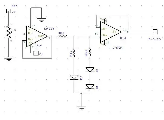
The potentiometer on the left of the circuit below is actually the output of a digital potentiometer designed for audio volume control, so its outputs are internally configured to offer 64 logarithmic steps, from 0dB to -64db. I can't change that. Now as it turns out, I need to use the output to control an audio amplifier that has an internal DSP processor, which accepts 0-3.2VDC to control its audio volume. That amplifier currently gets that voltage from a linear potentiometer, so it is internally doing its own linear to log conversion. So using the circuit shown without the diodes, with just R11 and R12 used as a simple voltage divider to convert my 0-12V to a 3.2V range, it works but the response is less than ideal. Since the output of my digital pot is advancing the voltage in 1 dB steps, the "steps" become audibly noticeable in that amplifier's output level, especially as the higher volumes are reached. So what I need to do is convert the logarithmic steps to some approximation of linear, meaning I need an anti-log function.

So I'm thinking of approximating an anti-log curve with a couple of diode networks as shown. Basically, the output voltage will initially follow the input voltage, but then rise progressively slower as D2, and then later the D3-D4 pair begin to conduct. It seems to work well enough to make the volume control sound more responsive, but somehow the circuit just seems to be a "hack" to me. Can anyone suggest a more eloquent solution that doesn't involve a huge amount of additional parts? enter image description here
Addendum... After playing trial and error with the above circuit all day, feeding it with a linear ramp and comparing input to output, I decided it was too difficult to optimize. Should the max reference voltage (12 V in the above) change at all, too many resistors have to change to duplicate the desired response. But on a whim I came up with this. I honestly have no idea if I'm really approximating an anti log (or log) response with this configuration, but I found it very easy to "tune" to a desired response, as long as the max input reference voltage was at least 2 or 3X the desired final output max. The gist is, as the input POT was adjusted higher, the output would gradually diverge from the input, so that input changes had progressively less affect on the output. The final test of course was to actual try it with an audio signal through the voltage controlled amplifier, and I thankfully found the digital POT control to be much more natural.

I'd still welcome comments on why this seems to be working so well, whether I am indeed approximating the non inverting log curve I'm after, and whether it could be done simpler. But bottom line, if anyone else runs into a similar problem, this does seem to work VERY nicely... at least to my ears!

enter image description here

Another addendum: For the benefit of anyone following this in need of a similar circuit, I need to point out the the LM324, despite being a common choice for single supply OP-AMP circuits, turned out to be a poor choice for this otherwise good circuit. The reason being, this OP amp is based on internal BJT transistors, and so it really can't "drive" any output below 0.6 volts. In my case, even though I didn't need the LOG response curve to start below that point, the circuit still needed to output 0-3 volts into an existing circuit that had a small positive bias current, and so I was not able to adjust the output down to zero, even if I grounded the final OP amp used as a buffer). So I will likely replace the quad OP amp with something like the Texas Instruments TLC274, because being FET based, its output Voltage Range actually does Include the Negative Rail

skrrgwasme
  • 828
  • 8
  • 32
Randy
  • 3,205
  • 3
  • 21
  • 38
  • I was at the point of editing your question to say "elegant" in place of your "eloquent", but I'd like to see someone rise to the challenge of making their solution truly eloquent. ;-) – Asmyldof Nov 17 '15 at 18:43
  • LOL!!! Well, most good engineers are lousy at spelling, so hopefully I'm in good company! – Randy Nov 17 '15 at 18:48
  • I'm too lazy to calculate through your specific problem, but for all the maths on log/exponential amplifiers using the exponential properties of a transistor, you could look at this: http://www.electronics.dit.ie/staff/ypanarin/Lecture%20Notes/DT021-4/6LogAntiLogAmplifiers.pdf – Asmyldof Nov 17 '15 at 18:55
  • 2
    A string of diodes with ressitors sprinkled between them like you have there is a pretty standard approach, don't call it a hack. Simple, cheap, easy to define a non-linear law by ressitor choice, what's not to like? (blamed keyboard won't spell ressitor!) – Neil_UK Nov 17 '15 at 19:02
  • That's a log amp at best and never an anti-log amplifier - think about it - if the voltage went from 1V to 2V at the input, the antilog output would go from 10V to 100V and what you have is the exact opposite. – Andy aka Nov 17 '15 at 19:17
  • Your proposed circuit aint too bad ,There isnt a lot of simplification to be done. – Autistic Nov 17 '15 at 19:24
  • @Asmyldof - The math on things like this frustrates me too, especially because in the end you can often "dial in" a better response visually or audibly in half the time. I have seen several seemingly simple diode or transistor/op-amp circuits, but they are all inverting in nature, so would require VERY careful balancing to set a reliable zero point. – Randy Nov 17 '15 at 19:32
  • @user44635 we'll I appreciate that its not considered a total hack. Like I said it does seem to work. Just seems there might be a better way I'm missing. – Randy Nov 17 '15 at 19:43
  • @Andyaka you are 100% right. I always manage to get analog stuff backwards. – Randy Nov 17 '15 at 19:45
  • @Autistic -- well its simple, but I just thought there might be a non inverting op-amp / diode based configuration that would give me a true log response. Maybe I have to lear that when I get something to work, its OK to STOP! – Randy Nov 17 '15 at 19:46
  • @Andyaka you are 100% right. What confuses me then is the fact that the digital pot is specified to output a LOG response, (1db per step), and I am trying to "un-do" that for the circuit that expects a linear input. But if my circuit is a "log" amp, then are you saying the digital pot actually has an "anti-log" response? – Randy Nov 17 '15 at 19:50
  • Beats me @Randy - I started reading your question and I began to glaze over!!! – Andy aka Nov 17 '15 at 20:54
  • Have you got the audio pot wired the correct way round i.e. A and B cannot be interchanged like a linear pot. – Andy aka Nov 17 '15 at 21:36
  • @Andyaka Yes... it is correct. If fact if I use that digital pot the way it was intended to be used (for an actual audio signal) its is extremely smooth and obviously true its 1db / step characteristic. Btw, I'll be posting an edit in about 2 minutes, showing my findings, after playing with this circuit all day. Hopfully I won't gl;aze over your eyes. ;-) – Randy Nov 18 '15 at 02:08
  • Q1 is *subtracting* a voltage from the output of the first amp that is proportional to the log of the input of that amplifier (for an increasing input voltage). So you don't have an antilog function, you have an (effectively) -log function. – Peter Smith Nov 18 '15 at 10:52
  • 1
    Thanks @PeterSmit. I see that the reason i was confused was because the data sheet for the digital pot, which is my source, gave the impression it had a "LOG" response, because each 'step" was 1DB. I needed to revere that, so I thought I was crafting an anti-log circuit. But now that i think of it, it is the pot that really has the anti-log response, and my "log" amplifier is basically needed to convert it to linear. Its too bad I go that wrong in the title, because the information in my OP is less useful due to my inaccurate title. – Randy Nov 18 '15 at 15:24
  • As I pointed out in my addendum today, the only flaw in my circuit now is my poor choice of the LM324 OP amp. Since its output stages are based on ordinary (BJT) transistors, it really can't "drive" the output below 0.6V. I'm thinking now of replacing this with a pin OP amp like the Texas Instruments TLC274, whose output Voltage Range actually does Include the Negative Rail. Can anyone confirm this OP amp would solve the problem I'm siting? – Randy Nov 19 '15 at 18:10
  • As @Asmyldof's link shows, this works best by putting the transistor in the feedback loop. – Ben Voigt Dec 07 '15 at 04:51

1 Answers1

2

Your 2nd circuits (with the NPN and R divider) is a good approximation of a log circuit. This is because when the input opamp generates a voltage substantially above 0.6 V, the current in the 4.7k is proportional to the voltage, and so the V across the NPN is proportional to the log of that current. The 100k & 10k give a multiplier effect, so in fact, your transfer function is closer to VOUT = K*26mVln(Iin/Is), where Iin = (VIN-0.7)/4.7k. 'Is' is hard to find directly, but if you measure (guess) VBE at 1 mA (say 0.6 V), the equation can be rewritten as VOUT = K[26mV*ln(In) + 0.6], where 'In' is in mA.

K is the gain from your R divider -- with 'Contour' =0, it's 1; with 'contour' = 20k, it's 3.

Note that this circuit will change over temperature --if the NPN heats up by (say) 30 deg. C, that's equivalent to about a 10 dB reduction in volume (when you go through math).

jp314
  • 18,395
  • 17
  • 46
  • Thanks. Thats a good confirmation that the idea is sound. And as I've switched to a TLV274 OP amp, which is FET based and has a much stronger pull down capability, the circuit works much more predictably down at sub-volt levels. – Randy Dec 08 '15 at 03:58