This is not a complete answer, but more a list of thoughts on the subject.
So first, you need to read the datasheet for the batteries! In there you will find the important information such as battery charging currents. I'll take this datasheet as an example. Here you can see that the battery has several charging modes and the specified currents for each of them as well as control parameters. So this type of battery, as well as other NiMH batteries, are charged using constant current, so a "simple" DC charger won't work. You'll need a constant current source for charging the battery and let the battery determine the voltage. There are many constant current sources, but the simplest thing that comes to my mind right now is a simple LM317 regulator in constant current mode.
Now since you have 3 cells in series, this will present some problems. The current through them will be same, so one current source may be enough, but the voltage in each cell may not be same as in the other two cells. You could ignore the problem, but that will be more expensive in the long run, since individual cells in the 3 cell battery may die more rapidly. In my country at least when price of individual NiMH cells is taken into account it turn out that much cheaper option is to use a balancer too. So the idea is that you'll have four additional contacts installed so that voltage of each cell can be measured. Then you can use the leads to discharge individual cell so that it matches the voltage of other two cells. I'm sure that it can be done using discrete components only, but I thing that right now the simplest way would be to use a microcontroller which would control the charging process. You should program it in such way that it can control power access to the LM317 (or whatever you pick) and that it can provide access to each individual cell too. Then you can discharge the cell using a resistor. I thing that it would be easiest to get use FETs for that, since they have low resistance when fully on and don't use current form the microcontroller.
Next you'll need to determine how long the charge process should last. The datasheet I linked has several options and each of them has its own good and bad sides.
The simplest way would be to just slowly charge the battery at (in my example) 70 mA and use the microcontroller as a timer. When the time passes, it should disable the power supply to the charging circuit. Good side of this is that you have a simple way to determine when you should stop charging and the bad side is that charging takes 16 hours.
Next we heave the trickle charge. You simply provide 35 mA to 70 mA and wait. The good side of this is that you shouldn't suffer a catastrophic failure of battery if it gets overcharged and that you don't need a stop circuit at all but the bad side is that it's even slower than slow charge and that, from what I've heard at least, long term trickle charge isn't too good for the battery.
After that we have the voltage change method and temperature change method. So basically when you reach the temperature and voltage change parameters specified, it means that the charging is complete. It is generally the best method for the cells themselves, but it is difficult to implement. You'd need a temperature sensor near the battery and you'll need a way to drive it using the microcontroller. It can be a simple thermistor or a dedicated temperature measurement integrated circuit. It also needs to be close to the battery in order to get good temperature. In addition to that you'll need to track the voltage change. If you plan to implement balancer, than this would only require a minor modification to the system because you'll need to measure the voltage of the whole battery too and then compare them over time. A big downside of this is that the battery voltage dip which indicates end of charge is not very pronounced so it can be difficult to detect. Also newer NiMH cells tend to emit large amounts of heat when fully charged so this makes the temperature change method more precise.
Here is a very rough sketch of what a relatively simple charger would look like:
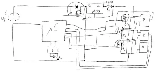
The "B" blocks on the circuit are there to measure voltage. Almost any microcontroller with an ADC can be used to easily measure voltage and there are numerous tutorials available, so use them to make such a circuit. You can get the whole battery voltage by adding the 3 voltages you get from each cell which could make the measurement a bit easier in cases when battery voltage is higher than microcontroller voltage. Using a 5 V microcontroller could help here.
The "D" block is there to measure the resistance of the thermistor which can be used to detect when the battery is fully charged. I also left it out, but it shouldn't be too hard to get a circuit for that.
I also left out any specifics the microcontroller may need like decoupling capacitors, crystal, its own regulator and so on.
The equation which can be used to get the value of the \$R_1\$ resistor is:
\$R_1=\frac{1.25 \mbox { }V} {I}\$ where \$I\$ is needed current. \$C_1\$ is the capacitor from LM317 datasheet.
\$R_B\$ are the resistors used for discharging the overcharged batteries. The value should be determined using several factors like the cell's maximum discharge current, the amount of time each cell should be balanced for, power ratings of available resistors and so on.
Input voltage \$U_1\$ should be at least 3 volts above the maximum voltage expected on the terminals of the LM317. Do note that NiMH cells can in certain (abnormal) situations reach as much as 1.7 V per cell, so input voltage should be determined with that in mind.
Another thing that should be added here would be pull-down resistors on all transistors so that gate voltage is left in known state when the microcontroller outputs low.