4

I have two MOSFET circuits; one is working and the other fails and I'm not sure why. I just want to turn on/off the LED, nothing special, no fast switching.

Below is the working circuit (series gate resistor):

schematic

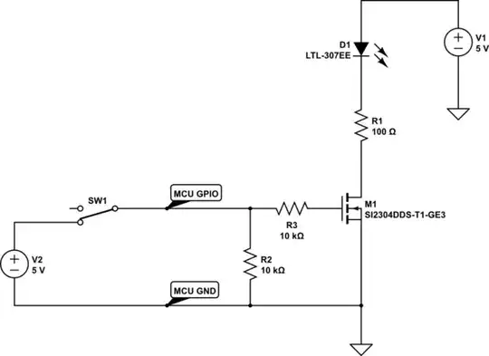
simulate this circuit – Schematic created using CircuitLab

Below is the non-working circuit. By non-working I mean when I apply a '0' to the gate, there is 2V sitting on the gate and the LED dimly comes on. Why is this happening?

schematic

simulate this circuit

I understand that a MOSFET has high gate impedance and a gate resistor is not a necessity but I wouldn't expect the MOSFET to completely not work right. Am I missing something?

Craigfoo
  • 229
  • 1
  • 10
  • Is this the same circuit with and without the 10K gate resistor or two different MOSFETs? If the latter is the case, does it work with the gate resistor added? Also, what MCU are you using? – Fizz Nov 12 '15 at 17:51
  • And how is this constructed physically? Breadboard, 4-layer PWB, solder tacked, ...? – The Photon Nov 12 '15 at 17:55
  • It's the same exact circuit; one with the 10k gate resistor, one without. To be honest, I didn't test with the actual MCU but I have 5V power supply tied to a button where I can mimic the MCU GPIO. This is just on a blank 0.1" spacing thru-hole PCB and the surface mount parts are soldered to the pads. A standalone circuit. – Craigfoo Nov 12 '15 at 18:02
  • Well you may have ESD'd it when you were working on it. http://electronics.stackexchange.com/a/69225/54580 – Fizz Nov 12 '15 at 18:35
  • Ok, I've tried the circuit without the series gate resistor with my Arduino and it's working correctly, completely switching on and off. I'm starting to think my power supply has some kind of high frequency, high voltage spike when I turn it on and it killed my FETs. When I added the series resistor, it limited the inrush current and therefore didn't kill it. Plausible? – Craigfoo Nov 12 '15 at 18:48
  • 1
    I took a look at the output of the power supply on my 100Mhz scope and I see a ringing of 25Mhz on start up. It only peaks around 6.64V though. The datasheet says the gate resistance at 1Mhz is 4.4 Ohms and the part can only dissipate 1.1W. That may be the issue. Does this seem right? – Craigfoo Nov 12 '15 at 19:09
  • How long were the wires from the button? – Andy aka Nov 12 '15 at 19:15
  • 1
    I had a 19" jumper from the power supply to the button then another 19" jumper from the button to the gate of the MOSFET. – Craigfoo Nov 12 '15 at 19:21
  • All I can tell you is that if everything is put together on a reasonably small board, you probably don't need the gate resistor with a FET. When I use FET's like this, I don't usually put in a gate resistor. Personally, I would probably use a BJT for this application. The BJT WOULD need a base resistor (maybe like 2.2k). I think 100 Ohms is a little small for R1. You may burn up your LED. I would go up to 150 or something. – user57037 Nov 13 '15 at 02:54
  • 3
    You are getting parasitic oscillations which can be destructive .Gate resistance is the accepted first line of defence against parasitic oscillations .This is why your version with the gate resistor survives. – Autistic Nov 13 '15 at 05:56
  • 1
    You're right on the LED resistors. I meant to put a 220 Ohm, just didn't do it when I drew the circuit. – Craigfoo Nov 13 '15 at 17:18

0 Answers0