Does anyone know of a Voltage Controlled Current Source IC? Or do you know how I can build one with as few other components as possible taking up a minimal amount of space?
current range needed is from 0mA to 350mA
Does anyone know of a Voltage Controlled Current Source IC? Or do you know how I can build one with as few other components as possible taking up a minimal amount of space?
current range needed is from 0mA to 350mA
Since you haven't specified output impedance, accuracy, or much anything else except as few components as possible, this is what you want:
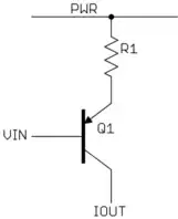
This makes use of the propoerties of a bipolar transistor where its collector current is largely not dependent on collector voltage, and the B-E drop is reasonably fixed. The voltage on the emitter will be close to Vin + 700 mV. The power voltage minus that will be across the resistor. That voltage divided by the resistor value will be the current thru the resistor, which is close to the collector current.
Let's say you want the 0-350 mA output current range controlled by a 3.5 V range of voltage. In that case, R1 would be 100 Ω, and the control voltage range would be PWR - 700 mV to PWR - 4.2 V.
This isn't what I would call a "precision" current source, but it is actually good enough for many real applications. It can be made more precise by putting a opamp around it to more accurately control the voltage across the resistor. Once you have that, you can use a PFET instead of a bipolar transistor because the feedback will compensate for the G-S voltage not being as fixed as the B-E voltage of a bipolar transistor. The advantage of a FET is that the drain current equals the source current (and therefore the resistor current), whereas with a bipolar the collector current is the emitter current minus the small base current. However, since your primary goal is simplicity without mention of other parameters, such more complicated topologies would just be overkill.
What Peter said.
NB the following is not just a LMGTFY answer (although looking at Google before you ask questions like that is always wise.) The following points out a feature which many aren't aware of.
Going to Google and searching for "voltage controlled current source" (try with and without quotes) and then changing to images (or change first) produces A vast number of images of voltage controlled current sources AND each one is hot linked to a related webpage. A vast resource. Not all of these will be useful or relevant - but many will be.
Via Google images search:
This webpage VCVS design
Says
Relating to this picture.
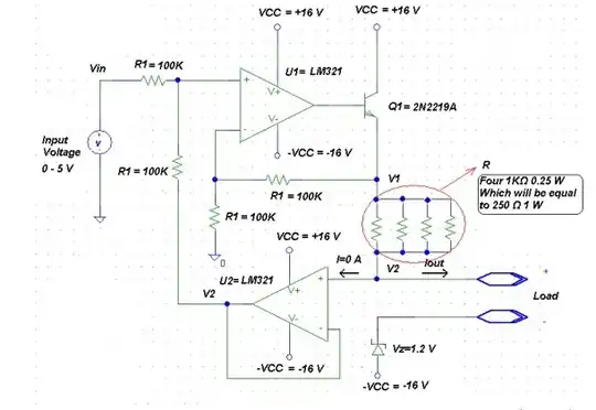
From this page you get the following diagram which is close to what Mike was suggesting.
And MUCH more - see images page above.
I believe all the solutions on this page are ground-referenced. That is, if there are long wires, less than ideal ground impedance, high ground currents or something they won't be precise.
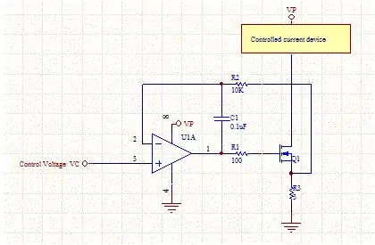
But this can be eliminated by so-called Howland current pump. The key benefit here is that it does not require the load to be connected to any power rail. Essentially, it's a differential amplifier. Please have a look on the following schematic.
R5 is the current sensing resistor, R6 is the load. The rest (R1-R4) are part of the differential amplifier. The voltage across R5 is equal to V3. Hence, the current through it will be \$I_{R5} ~= V3 / R5\$. If R6 << R4, then \$I_{R5} \approx I_{R6}\$. In this schematic there is always a small output error because part of the output current flows through R4 as well. But this can be eliminated using, e.g., voltage buffer between R4 and R5.
[![Howland charge pump (minimal version)[1]](../../images/3844803766.webp)
For more information see the following materials:
"What is a Howland Current Pump?" by Kelvin Le
"Difference Amplifier Forms Heart of Precision Current Source"
"AN-1515 A Comprehensive Study of the Howland Current Pump"
"Tame those versatile current source circuits"
"EEVblog #579 - Precision Low Current Source" (not Howland pump, but interesting)
I'd just use an op-amp and a current sense amplifier.
That's where I'd start, at least. The basic idea is that you use a current sense resistor to convert current to voltage, the current sense amplifier gains it up and removes the large common mode voltage, then the op amp looks at the difference between the set current and the detected current and adjusts the gate drive accordingly. The transistor acts like an inverter stage, so the feedback gets connected to the op amp's + instead of - so you don't oscillate.
You'll probably need to test its stability over various noise frequencies and adjust the compensation capacitance, or replace it with a different compensation network. You might also want to put in a resistor divider feedback loop to cut the op amp's gain down, but I'm not sure you need to (the main loop may be enough to do that).