0

I'm just starting out with electronics, this should explain why my "schematic" is so readable. I'll attach it and explain further.enter image description here

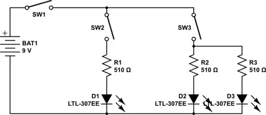
I know how to create a simple circuit with the main slide switch and either of the LEDs, but I honestly have no idea on how would I create 3 parts that are powered by one source but aren't connected "in one line" (Is that called a linear circuit?).

My second problem, that I have not illustrated in my schematic, is - how, if it's possible at all, could I create the potentiometer control the 7 segment displays so they display random numbers (or just light up random parts of the screen, really). The display should change only when potentiometer is turned.

I hope that I make some sense and you can give me some tips on where to start. Thanks!

MarkU
  • 14,413
  • 1
  • 34
  • 53
  • Re:"Is that called a linear circuit?" -> series. And it's actually fine to put LEDs in series, but not so fine in parallel. – Fizz Nov 01 '15 at 22:18
  • 1
    You want the lot, all at once ;-) I suggest you start with just a switch, a led and a battery then step by step add more. Learn how to draw a proper schematic because if you can do that, you also know how to connect everything. Have a look at the many similar projects on the internet and learn. Start at the basics, it is no shame, we all did that. – Bimpelrekkie Nov 01 '15 at 22:19
  • Start with a switch LED, battery _and a resistor_. The resistor is needed to limit the current through the LED - see the many questions on this site re LEDs and resistors. – Peter Bennett Nov 01 '15 at 22:25
  • What you've drawn there is a pretty good flow diagram of how you intend power to flow from the battery. What's missing is the ground return connections; see Peter Bennett's answer. – MarkU Nov 01 '15 at 22:41

2 Answers2

2

The circuit that you show in your sketch has three branches connected in parallel - something like this (although I only show two branches):

schematic

simulate this circuit – Schematic created using CircuitLab

In this circuit, SW1 is the main power switch - it turns everthing off.

SW2 will turn D1 off and on, if SW1 is on.

SW3 turns D2 and D3 off or on, if SW1 is on.

The resistors R1, R2, and R3 limit the current through the LEDs to about 13 mA.

As Respawned Fluff indicates, some more complex circuitry is required to drive the 7-segment displays.

Peter Bennett
  • 57,014
  • 1
  • 48
  • 127
1

Re:"Is that called a linear circuit?"; it's called series. And it's actually fine to put LEDs in series, but not so fine in parallel.

My second problem, that I have not illustrated in my schematic, is - how, if it's possible at all, could I create the potentiometer control the 7 segment displays so they display random numbers (or just light up random parts of the screen, really). The display should change only when potentiometer is turned.

For this you'll need an ADC (analog digital converter) and a display driver. There are some ICs (integrated circuits) that do both in one package, e.g. ICL7107. This one is fairly used by hobbyists. For a more modern solution, you could use a microcontroller for interfacing (and there are some with built-in ADCs), but that will require some programming skills as well.

Fizz
  • 14,355
  • 2
  • 43
  • 97
  • Thanks for the great answer! I'll certainly look into ICs, a microcontroller seems like a bit too much for this. Arduino costs a bit too much and I don't have a microcontroller burner. – Cascade Nov 01 '15 at 22:42