5

The ordering of the segment pins (14-17, 20-23) on the MAX7219/MAX7221 common-cathode LED display driver is unusual, to say the least:

enter image description here

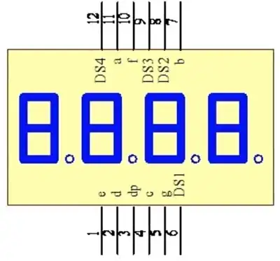
The order of these pins is similar, but not identical, to the standard pin layout used by 4-position 7-segment displays, e.g.

enter image description here

It's similar enough that I feel like there should be some really neat way to lay it out on a PCB, but if there is, I can't seem to figure it out. Is there a particular board layout that this pin ordering is supposed to allow for? If so, what does it look like? (Or is this part intended for a different type of display?)
3 Answers3

3

Looks like a tangle to me. Sometimes you just have to suck it up and route it regardless. If you really want a nice layout, slap it down and re-route it 4 or 5 times, trying to move components around to reoptimize. You'll eventually pick up enough tricks to do your optimal layout for this design.

Daniel
  • 6,168
  • 21
  • 33
1

There is not even a de facto standard for 7-segment LED character pinouts. At best, you have some commonality between characters made by the same manufacturer.

Multi-character sets are even more varies than single character.

1 This is based on my own observation. Over the last couple years, I have designed 3 different 7-segment LED display boards for production. Boards were based around other ICs, other than around Maxim's.

Nick Alexeev
  • 37,739
  • 17
  • 97
  • 230
  • Really? Every display of this general type I've examined (4-position, 7-segment with decimal point, common-anode or common-cathode) has had essentially the same pinout. Either I've been very lucky in the displays I've examined, or a *de facto* standard has emerged… –  Oct 29 '15 at 23:22
0

I've routed PCBs using MAX7219/MAX7221 and a few multiplexed LEDs, both common anode and common cathode.

After multiple attempts at layout, I came to the view that it is optimised to minimise the chances of awful layouts.

Concretely, because both sides of the MAX72xx and LED have both row and column (source/sink) pins, and each set of pins are 'interleaved', I could rotate the two parts (MAX and LED) and come up with an okay layout no matter what the orientation of the two parts.

I tried most orientations with the MAX72xx under the LED, and a couple with the MAX72xx off to one side. It was always relatively straightforward to route on a 2-layer PCB.

I never found one arrangement that produced a very neat layout. Some orientations were slightly better than others by a couple of tracks, but nothing was 'stand out'.

I thought about that, and decided it was pretty clever.

gbulmer
  • 10,040
  • 20
  • 29