7

A flip flop is a sequential circuit and it stores a 1-bit value, but it is designed using only basic, universal gates and a feedback circuit. How then is it able to store or handle a 1-bit value?

I thought that it is due to clock usage but I don't know the exact reason.
Is my assumption is correct or not?

Gouse Shaik
  • 1,153
  • 3
  • 10
  • 17

2 Answers2

8

The easiest flip-flop to understand is the SR (Set-Reset) flip-flop:

SR flip-flop

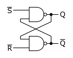
Normally both inputs are high. When you pull the \$/S\$ input low, output \$Q\$ will go high regardless of the other input. Since the other NAND gate sees now a high level on both its inputs the \$/Q\$ output will be low. Now, even when \$/S\$ goes high again, the other input will be low, so the output \$Q\$ retains its state. That's the most easy way to make logic "remember" something.

Starting from the SR flip-flop you can make more complicated registered logic, where the D flip-flop is the most used.

D flip-flop

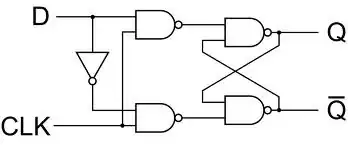
This circuit is sometimes presented as an edge-triggered D -flipflop, but it's really level triggered, where \$CLK\$ is used to gate the \$D\$ input. If \$CLK\$ is low both inputs of the SR flip-flop are high, and it retains its output state. When \$CLK\$ goes high the \$D\$ input decides whether \$/S\$ or \$/R\$ goes low, and the output will set accordingly, thus remembering the state of \$D\$ when \$CLK\$ went high. The difference with a real edge-triggered D -flip-flop is that the output will change with the input as long as \$CLK\$ is high. To make it an edge-triggered flip-flop you'll have to include some feedback that makes the \$CLK\$ go low again immediately after going high. The D-type latch, as it's called, will remember the input state at the time the \$CLK\$ input goes low; i.e. the output will stop changing after the \$CLK\$ goes low again.

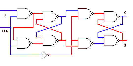
This is an edge-triggered D flip-flop:

edge-triggered D flip-flop

stevenvh
  • 145,145
  • 21
  • 455
  • 667
  • the last lines in ur answer was not understandable to me,can u xplain it breifly – Gouse Shaik Sep 21 '11 at 10:39
  • @Gouse - The output follows the input while CLK is high, but doesn't change when CLK is low. So if you can make the CLK signal into small pulses the output will change during this small pulse, but remain unchanged afterwards. So the input is "frozen" at the time of the pulse. – stevenvh Sep 21 '11 at 10:55
  • @Dean - I appreciate your contribution, but my answer refers to NAND flipflops. – stevenvh Sep 21 '11 at 11:30
0

For those who are not engineering students (curiosity-seekers) I will try to get a metaphor in your mind: think of the set-reset flip-flop picture as a water park with water streams instead of electricity. The water flows in a circle, like a slide with some turns. In this (simple) metaphor, there are two possible flows, circles or paths through the water park. One path/circle represents a 1 the other path represents the 0 (in your truth table). If you want to change the path or flow (state) you will either sent a signal through S or through R to adjust the gates. The gates are the two "bells" in the picture. If you add complexity it needs more gates(bells). Hope it helps to get the idea!