0

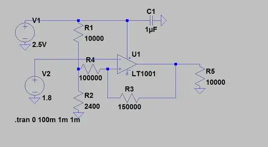
I want to translate or shift 1.8V to about 2.5V. Now, there are 2 ways I can go about with it. Use an op-amp based circuit as shown below -

Opamp level shifter

Mosfet circuitry - MOSFET circuitry.

Which is more efficient and why ? In one of my posts(Link) one of the contributors stated - "The only real downside is a semi decent driver is required, a weak one won't cut it." for the MOSFET circuit. Why so ?
Board-Man
  • 1,919
  • 1
  • 26
  • 70
  • 7
    There's certainly more than two ways to do it - there are dedicated level shifter ICs too. And an opamp is an odd way to do it if your signals are digital. The best solution depends on the voltage levels involved, the signalling rate, and whether or not you need it to be bidirectional. – Nick Johnson Oct 28 '15 at 15:54
  • Unfortunately I need it to be Hi-Rel. Its unidirectional. So, I am basically changing 1.8V to 2.5V. The rate is UART baud rates of a max of 460800bps. – Board-Man Oct 28 '15 at 15:56
  • What is "Hi-Rel"? – Nick Johnson Oct 28 '15 at 16:03
  • hi reliability. – Board-Man Oct 28 '15 at 16:03
  • Why would an opamp be intrinsically higher reliability than any other solution? – Nick Johnson Oct 28 '15 at 16:04
  • I am asking the same. Which is more reliable and better and why. – Board-Man Oct 28 '15 at 16:05
  • 2
    I cannot see a reason NOT to use a dedicated levelshifter IC, they're reliable and cheap. What you're trying to do here looks to me like a recipe for failure. This is what is inside a proper leveshifter: http://images.elektroda.net/64_1181121303.jpg No way you're going to make that cheaper and better with discrete components. – Bimpelrekkie Oct 28 '15 at 16:05
  • Unfortunately, I dont have hi rel voltage level translators that can shift 1.8V to 2.5V. Pls mind, I am looking for hi-rel components. – Board-Man Oct 28 '15 at 16:06
  • 1
    @VinodKaruvat - Please define hi-rel. Is there a particular standard you're working to? Specific environment? Ordinarily, hi-rel implies purchase of carefully pre-screened parts. It would help if you could provide some background as to ultimate use of the circuit. – WhatRoughBeast Oct 28 '15 at 16:23
  • It is for an aerospace application. @FakeMoustache. Why do you say its a recepie for disaster in the technical sense please? – Board-Man Oct 28 '15 at 16:26
  • 1
    If you have specific constraints on what parts you can use, you need to state that in your question. – Nick Johnson Oct 28 '15 at 16:34
  • 1
    @VinodKaruvat - Aerospace does not necessarily rule out commercial parts. I've flown suborbital missions with COTS electronics parts and they worked fine. I've provided multiple airborne sensors with COTS (had to pay attention to temperature ratings, though) and the systems had multi-year lifespans. So, what exactly are your requirements? – WhatRoughBeast Oct 28 '15 at 16:53
  • What is the signal being shifted? The single FET level-shifter works well for bidirectional, low-speed signals such as in I2C. Otherwise, if it is bidirectional, a dedicated IC would be easiest and best. If it is unidirectional, then a simple comparator circuit would work well if you are opposed to using level-shifter IC's. I see no reason to use an op-amp. – user57037 Oct 28 '15 at 17:31
  • Did you know that you can alt-click in LTspice to get the power plotted for a component? Simply add up the power dissipation for all components in each circuit to find out which of the two consumes more. (I assume this is what you mean by "more efficient") Also you're missing a supply connection for the opamp in your first circuit. – Fizz Oct 28 '15 at 17:52
  • Also you didn't put any specific MOSFET model in there, so how are we supposed to know what gate charge it needs, how fast it switches, etc.? Also what signal speed are you considering? By the, [according to NXP](http://www.nxp.com/documents/application_note/AN10441.pdf) the bottom circuit is okay up to about 400kbit/s. – Fizz Oct 28 '15 at 17:56
  • But that's shifting between 3.3 and 5V. A lot depends on the MOSFET part used at lower voltages. Also the speed that you want [determines the pull-up resistors](http://www.onsemi.com/pub_link/Collateral/AND8449-D.PDF) and that in turn affects power dissipation. – Fizz Oct 28 '15 at 18:02
  • What is your input signal and what is your required output signal - it's simple enough surely? – Andy aka Oct 28 '15 at 19:10

1 Answers1

0

Below please find High-rel level shifter circuit. This should work fine at the baud rate you mentioned. Select R3 based on acceptable rise times. Since I am not sure what incantations or rituals are required to create Hi-Rel components, I leave the selection of U1 to you. Hopefully you will also be able to source Hi-Rel resistors for R1, R2 and R3. You will also need a 0.1uF bypass cap.

High-rel level shifter

user57037
  • 28,915
  • 1
  • 28
  • 81